F I S H M A N A C O U S T I C M A T R I X ™
(8.7mm) outside the guitar's body for proper fit.
A set of adhesive backed clips has been provided to secure the pickup cable and battery leads inside the guitar once the endpin jack has been installed.
Prepare the Endpin Hole for the Jack
There are two ways to widen the endpin hole to accept the preamp.
Slow and Safe
If you have the time, this is the preferred method. Remove the endpin and widen the hole to size with a 15/32" (11.9 mm) reamer (available in the US & Canada through Stewart MacDonald,
OR ...
Quick & Clean
The objective here is to quickly drill out the endpin jack hole, with the endpin or other suitable plug in place. You may remove a loose endpin and refasten it in the endblock with cyanoacrylate glue before starting the procedure.
Note: We do not recommend this method for instruments with brittle
ornamental veneers (ex: abalone) around the endblock.
1.Apply masking tape around the endblock area to protect the instrument.
2.Locate an
3.Centerpunch a guide hole in the center of the trimmed endpin.
4.Drill a 1/8" (3.2mm) pilot hole through the endpin.
5.Line up a 15/32" (11.9mm) Spade bit in the pilot hole and begin drilling. Maintain a perpendicular plunge in relation to the instrument. Use steady (but not heavy) pressure, especially as the drill exits inside the guitar.
6.To avoid damage to the instrument, let the drill come to a complete stop before removing it from the hole.
Pickup & Electret Microphone
(use with the Fishman Blender System)
Microphone Shield to Ground ("G")
Pickup Shield to to Ground ("G")
REV. 4.0 | G | G |
IN | R |
Pickup Signal | Zener | |
to IN Pad | ||
Diode | ||
|
Microphone Signal
to Ring ("R")
Note: Before you install a microphone, check the manufacturer’s specific wiring instructions (color coding).
Additional Volume & Tone Controls
Fit the small dress washer and nut over the end of the jack, then insert a 3/32" Allen wrench through the small hole on the end of the jack. Tighten the nut with a 1/2"
Note: With the strap button in place, the end of the jack should protrude slightly, so that when a plug is inserted, it will snap securely in place.
Attach the Battery Clip
We recommend that you attach the battery clip to a small piece of hardwood approximately 1 1/2" x 1 1/2" x 1/2" (4cm x 4cm x 1.1cm) thick. Mark the screw hole locations on the block using the battery holder as a template. Drill the screw holes using the 5/64" (2mm) drill. Attach the battery holder using the two supplied 1/4" screws. Attach this assembly to the inside front block (neck block) using either wood glue or a gap filling cyanoacrylate such as Loctite® Black Max™.
Important! Although the supplied battery holder should provide adequate capacity to grip the battery at all times, we strongly recommend that you remove the battery when shipping your instrument. FAILURE TO REMOVE BATTERY COULD RESULT IN DAMAGE TO YOUR INSTRUMENT. Fishman will not be held responsible for any damage incurred to instruments from a loose battery.
Remove the plastic film from the back of each clip to expose the adhesive. Secure the cable/clips to the kerfed lining of the guitar.
Specifications |
|
Power Supply: | 9 Volt Alkaline battery |
Battery Life: | Natural I - 6,000 hours |
| Natural II - 6,000 hours |
Maximum Output Voltage: | 4V peak to peak |
Output Impedance: | Less than 5kOhm |
94 dB |
Discrete Component Design: FET low noise class A input stage, bipolar class AB output stage
All specifications subject to change without notice.
Solder the Wire Connections
1.Unscrew the shielding cap to access the preamp circuit board.
2.Strip 1/4" off the outside jacket of the pickup wire. Tin both the inner con- ductor and the ground wire.
3.Thread the pickup wire through the shielding cap.
4.Thread the pickup wire through the center strain relief hole, then solder the signal wire from the pickup (hot wire) to the pad marked "IN" on the preamp circuit board. Solder the ground wire from the pickup (shield) to the adjacent pad marked "G" on the preamp circuit board. (See Fig 1) Do not over heat the solder pads! Doing so may lift the pads from the circuit board.
5.Fasten the shielding cap to the jack. Be careful not to allow the shielding cap to come in contact with the end of the circuit board.
6.Lock the shielding cap to the first large hex nut.
Ground
TONE
20K Audio
1K
Resistor
.068 mF | V OLUME |
Capacitor | 20K Audio |
Troubleshooting
Symptom |
| Cause | Solution |
|
| Saddle is not completely seated. | Push the saddle down over the weak strings. |
|
| ||
|
|
|
|
|
| Bottom of saddle is uneven or out of square with its sides. | Check bottom of saddle for flatness and squareness. |
|
| Debris in the saddle slot. | Remove debris from the saddle slot. |
|
|
|
|
|
| Improper saddle fit (too tight or loose). | Make sure that the saddle has a sliding fit in the slot. |
Weak string |
|
| Do not use bone, ivory or other organic materials |
| Saddle material. | for the saddle material. We recommend the | |
|
| Fishman Cleartone™ | |
or strings |
|
| |
|
|
|
Figure 1
REV. 4.0
G G
Not enough downbearing pressure on saddle. | Follow the 50/50 rule. |
Pickup Shield
to Ground ("G")
G | G | ||
|
| ||
+ | IN |
| R |
Pickup Signal
to IN pad
Optional Stereo Wiring
The Fishman Switchjack™ switching endpin jack is integrated into the Acoustic Matrix™. A variety of stereo wiring options are available for pickup+microphone or pickup+pickup:
Two Pickups
2nd Pickup Signal to Ground ("G")
Pickup Shield
to Ground ("G")
REV. 4.0 | G | G |
|
|
IN | R |
Pickup Signal
to IN pad
2nd Pickup Shield to Ring ("R")
IN ![]()
![]() R
R
182![]()
![]()
Remove
1.8K Resistor
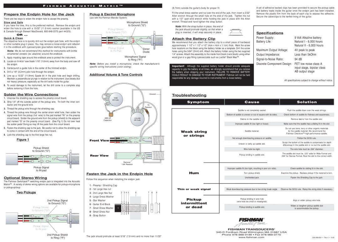
Fasten the Jack in the Endpin Hole
Follow this sequence when installing the endpin jack:
1 | - Preamp / Shielding Cap |
|
|
|
2 | - 1st Large Hex nut |
|
|
|
3 | - 2nd Large Hex Nut | 2 3 4 5 | 6 | 7 8 9 |
4 | - Large Dress Washer |
|
|
|
5 | - Star Washer |
|
|
|
6 | - Guitar End Block |
|
|
|
7 | - Small Dress Washer | 1 |
|
|
8 | - Small Dress Nut |
|
|
|
9 | - Strap Button |
|
|
|
The jack should protrude at least 5/16" (7.9 mm) and no more than 11/32"
|
|
|
| Uneven or belly up saddle slot. | Sculpt the bottom of the saddle to compensate for depth | ||
|
|
|
| differences in the saddle slot or | |||
|
|
|
|
|
|
| |
|
|
|
|
|
|
|
|
|
|
|
| Wire hole too tight. |
| The wire hole must be .094" diameter. | |
|
|
|
| Pickup binding in saddle slot. | The saddle slot must be .125" wide for Wide Format and | ||
|
|
|
| .094” for Narrow Format. Rout the slot to the correct width. | |||
|
|
|
|
|
|
| |
|
|
|
|
|
|
|
|
|
|
|
|
|
|
|
|
|
|
|
| Improper saddle fit (too tight, resulting in poor s/n ratio). | Check saddle for sliding fit in the slot. | ||
Hum |
|
| Torn pickup shield. | Examine the pickup. Replace pickup if the material is torn. | |||
|
|
|
|
|
|
|
|
|
|
|
| Unshielded jack. | Fasten the Shielding Cap to the jack. | ||
|
|
|
|
|
|
|
|
Thin or weak signal |
|
|
|
|
|
| |
|
| Weak downbearing pressure due to low string break angle. | Observe the 50/50 rule. Ramp the string slots if necessary. | ||||
|
|
|
|
|
|
| |
Pickup |
|
| Pickup binding in wire hole | Align or widen pickup wire hole. | |||
|
| (wire hole too small or misaligned). | |||||
intermittent |
|
|
| ||||
|
|
|
|
|
| ||
or dead |
|
| Pickup binding in saddle slot. |
| Widen or lengthen pickup saddle slot | ||
|
|
| to accommodate the pickup. | ||||
|
|
|
|
|
|
| |
|
|
|
|
|
|
|
|
|
| ® |
|
|
| ||
|
|
|
| FISHMAN TRANSDUCERS® |
| ||
|
| ||||||
|
|
| Phone |
| |||
|
|
|
| www.fishman.com | |||