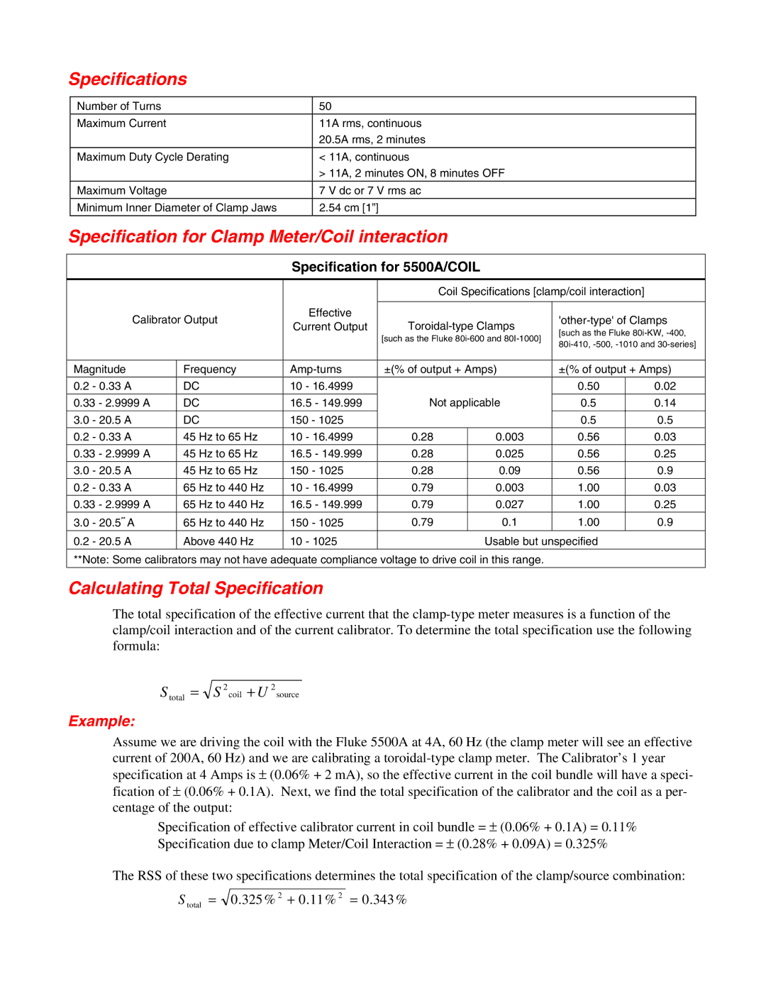
5500A specifications
The Fluke 5500A is a highly regarded calibration instrument in the field of electrical measurements, known for its versatility and precision. Designed for both laboratory and field use, this calibrator plays a crucial role in ensuring measurement accuracy across various applications. It is particularly favored for its ability to calibrate a wide range of electrical devices, including multi-meters, oscilloscopes, and other electrical instruments.One of the standout features of the Fluke 5500A is its ability to generate precise voltage and current outputs. This unit is capable of producing output ranges from microvolt levels up to high-voltage levels, making it suitable for a vast array of calibration tasks. With its high accuracy and stability, the Fluke 5500A ensures that even the smallest discrepancies in measurements can be corrected, contributing to overall equipment reliability.
The Fluke 5500A incorporates advanced technologies that enhance its functionality. Notably, it features a digital display that allows users to easily monitor and adjust the calibration parameters. The intuitive user interface simplifies the calibration process, enabling technicians to perform tasks quickly and efficiently. Additionally, the device supports a variety of output signals, including AC and DC voltage, resistance, and frequency, providing comprehensive testing capabilities.
Another significant characteristic of the Fluke 5500A is its automated calibration capability. This function enables users to run automated sequences, which reduce the time and effort needed for regular calibration tasks. The unit also supports remote control operation, allowing for seamless integration into automated test systems, further enhancing its versatility.
The Fluke 5500A’s robust design ensures that it can withstand the demands of both laboratory and field environments. Built with high-quality components, the device is engineered for durability, making it a reliable choice for calibration and testing in various settings.
In summary, the Fluke 5500A is a state-of-the-art electrical calibrator that combines precision, versatility, and user-friendly features. Its ability to generate various output signals, along with automated calibration capabilities, makes it an essential tool for professionals striving for the highest standards of measurement accuracy. Whether in a laboratory or field environment, the Fluke 5500A stands as a testament to modern calibration technology.

