®
80T-150U-7001K Probe Kit
Installation and Calibration Instructions for the 80T-150U
Probe Installation for the 80T-150U
1.Remove the top cover from the
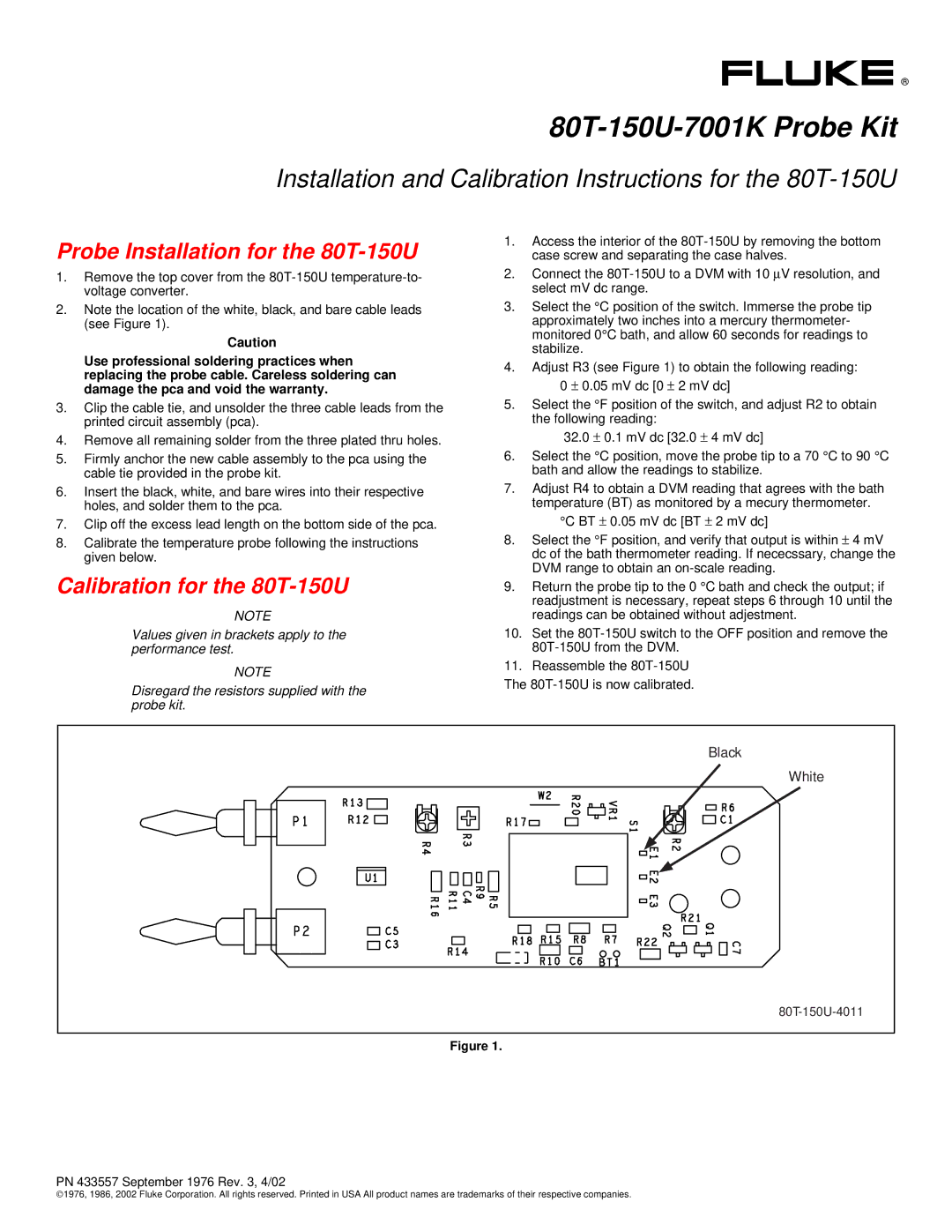
2.Note the location of the white, black, and bare cable leads (see Figure 1).
Caution
Use professional soldering practices when replacing the probe cable. Careless soldering can damage the pca and void the warranty.
3.Clip the cable tie, and unsolder the three cable leads from the printed circuit assembly (pca).
4.Remove all remaining solder from the three plated thru holes.
5.Firmly anchor the new cable assembly to the pca using the cable tie provided in the probe kit.
6.Insert the black, white, and bare wires into their respective holes, and solder them to the pca.
7.Clip off the excess lead length on the bottom side of the pca.
8.Calibrate the temperature probe following the instructions given below.
Calibration for the 80T-150U
NOTE
Values given in brackets apply to the performance test.
NOTE
Disregard the resistors supplied with the probe kit.
1.Access the interior of the
2.Connect the
3.Select the °C position of the switch. Immerse the probe tip
approximately two inches into a mercury thermometer- monitored 0°C bath, and allow 60 seconds for readings to stabilize.
4.Adjust R3 (see Figure 1) to obtain the following reading:
0 ± 0.05 mV dc [0 ± 2 mV dc]
5.Select the °F position of the switch, and adjust R2 to obtain the following reading:
32.0± 0.1 mV dc [32.0 ± 4 mV dc]
6.Select the °C position, move the probe tip to a 70 °C to 90 °C bath and allow the readings to stabilize.
7.Adjust R4 to obtain a DVM reading that agrees with the bath temperature (BT) as monitored by a mecury thermometer.
°C BT ± 0.05 mV dc [BT ± 2 mV dc]
8.Select the °F position, and verify that output is within ± 4 mV dc of the bath thermometer reading. If nececssary, change the DVM range to obtain an
9.Return the probe tip to the 0 °C bath and check the output; if readjustment is necessary, repeat steps 6 through 10 until the readings can be obtained without adjestment.
10.Set the
11.Reassemble the
The
Black |
White |
Figure 1.
PN 433557 September 1976 Rev. 3, 4/02
©1976, 1986, 2002 Fluke Corporation. All rights reserved. Printed in USA All product names are trademarks of their respective companies.