Light Icon | Description | |||||||||||
|
|
|
|
|
|
|
|
|
|
|
| The light flashes orange when packets are sent and received on |
|
|
|
|
|
|
|
|
|
|
|
| |
|
|
|
|
|
|
|
|
|
|
|
| the Ethernet port 1 and 2. |
|
|
|
|
|
|
|
|
|
|
|
| |
|
|
|
|
|
|
|
|
|
|
|
|
|
|
|
|
|
|
|
|
|
|
|
|
| Power indicator is blue when the FortiManager system is on. |
|
|
|
|
|
|
|
|
|
|
|
| |
|
|
|
|
|
|
|
|
|
|
|
|
|
|
|
|
|
|
|
|
|
|
|
|
| The light flashes blue when reading the boot device. |
|
|
|
|
|
|
|
|
|
|
|
|
|
Hard Disk Upper LED | Blue when the hard disk is properly inserted into the drive bay | |||||||||||
|
|
|
|
|
|
|
|
|
|
|
| and the FortiManager is plugged in to a power source. |
Hard Disk Lower LED | Flashes blue when reading and writing to the hard disk. | |||||||||||
QuickStart Guide
PS RST
![]() 2
2 ![]() 1
1
DISK DRIVE LEGEND | POWER |
ACTIVITY |
![]() HDD 1 (P0)
HDD 1 (P0) ![]() HDD 4 (P3)
HDD 4 (P3)
![]() HDD 2 (P1)
HDD 2 (P1) ![]() HDD 5 (P4)
HDD 5 (P4)
![]() HDD 3 (P2)
HDD 3 (P2) ![]() HDD 6 (P5)
HDD 6 (P5)
Visit these links for more information and documentation for your Fortinet product.
•Technical Documentation - http://docs.fortinet.com
•Fortinet Knowledge Center - http://kb.fortinet.com
•Fortinet Technical Support - http://support.fortinet.com
•Training Services - http://campus.training.fortinet.com
© Copyright 2009 Fortinet Incorporated. All rights reserved.
Products mentioned in this document are trademarks or registered trademarks of their respective holders.
Regulatory Compliance
FCC Class B Part 15 CSA/CUS02-40000-112745-20091027
11 March 2010
Package Contents
Connector | Type | Speed | Protocol | Description |
Port 1 to 4 | 100/1000 | Ethernet | Connection to the internal network. | |
CONSOLE | DB9 | 9600 bps 8/N/1 | Optional connection to the management computer. Provides access to the command line interface. | |
USB | USB |
| USB | For future use. |
|
|
|
|
|
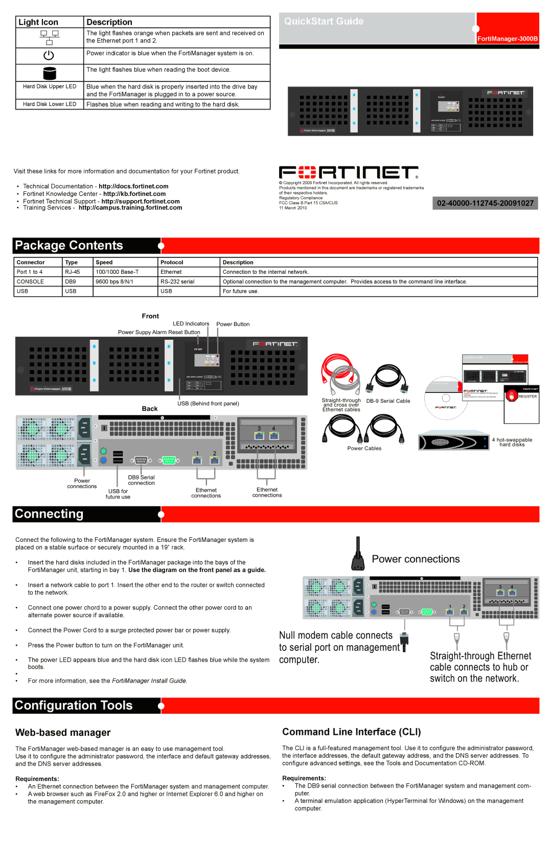
Front
LED Indicators Power Button
Power Suppy Alarm Reset Button
®
PS RST
|
| QuickStart Guide |
2 | 1 |
DISK DRIVE LEGEND | POWER | |
ACTIVITY | ||
HDD 1 (P0) | HDD 2 (P1) | Tools and Documenation |
|
| |
HDD 3 (P2) | HDD 4 (P3) |
|
EMPTY | EMPTY |
|
|
|
| Copyright 2008 Fortinet Incorporated. All rights reserved. |
|
|
|
| Trademarks | REGISTER |
|
| Products mentioned in this document are trademarks. | ||
| USB (Behind front panel) |
| ||
Back | and cross over |
|
| |
| Ethernet cables |
|
|
Power Cables
Power | DB9 Serial |
|
| |
connection |
|
| ||
connections | Ethernet | Ethernet | ||
USB for | ||||
| ||||
| future use | connections | connections |
Connecting
4
Connect the following to the FortiManager system. Ensure the FortiManager system is placed on a stable surface or securely mounted in a 19” rack.
•Insert the hard disks included in the FortiManager package into the bays of the FortiManager unit, starting in bay 1. Use the diagram on the front panel as a guide.
•Insert a network cable to port 1. Insert the other end to the router or switch connected to the network.
•Connect one power chord to a power supply. Connect the other power cord to an alternate power source if available.
•Connect the Power Cord to a surge protected power bar or power supply.
•Press the Power button to turn on the FortiManager unit.
•The power LED appears blue and the hard disk icon LED flashes blue while the system
boots.
•
•For more information, see the FortiManager Install Guide.
Power connections
Null modem cable connects |
| |
to serial port on management | ||
computer. | ||
cable connects to hub or | ||
| ||
| switch on the network. |
Configuration Tools
The FortiManager
Use it to configure the administrator password, the interface and default gateway addresses, and the DNS server addresses.
Requirements:
•An Ethernet connection between the FortiManager system and management computer.
•A web browser such as FireFox 2.0 and higher or Internet Explorer 6.0 and higher on the management computer.
Command Line Interface (CLI)
The CLI is a
Requirements:
•The DB9 serial connection between the FortiManager system and management com- puter.
•A terminal emulation application (HyperTerminal for Windows) on the management computer.