CROSSOVER NETWORK, SELECTOR SWITCH
1) FULL
At this position, the crossover network is bypassed, (Hz) control pot becomes ineffective, a flat response output against the input signal is obtained at the output connec-
tor. The crossover network outputs (HIGH, LOW) at each con- nector will be those set by the crossover frequency adjust- inig knobs.
2)HIGH
When this position is selected, the HIGH PASS signal whose cutoff frequency is set by the (Hz) knob, is obtained at the speaker output connector.
3)LOW
When set to this position, the LOW PASS signal whose cutoff frequency is set by the (Hz) knob, is obtained at the speak- er output connector.
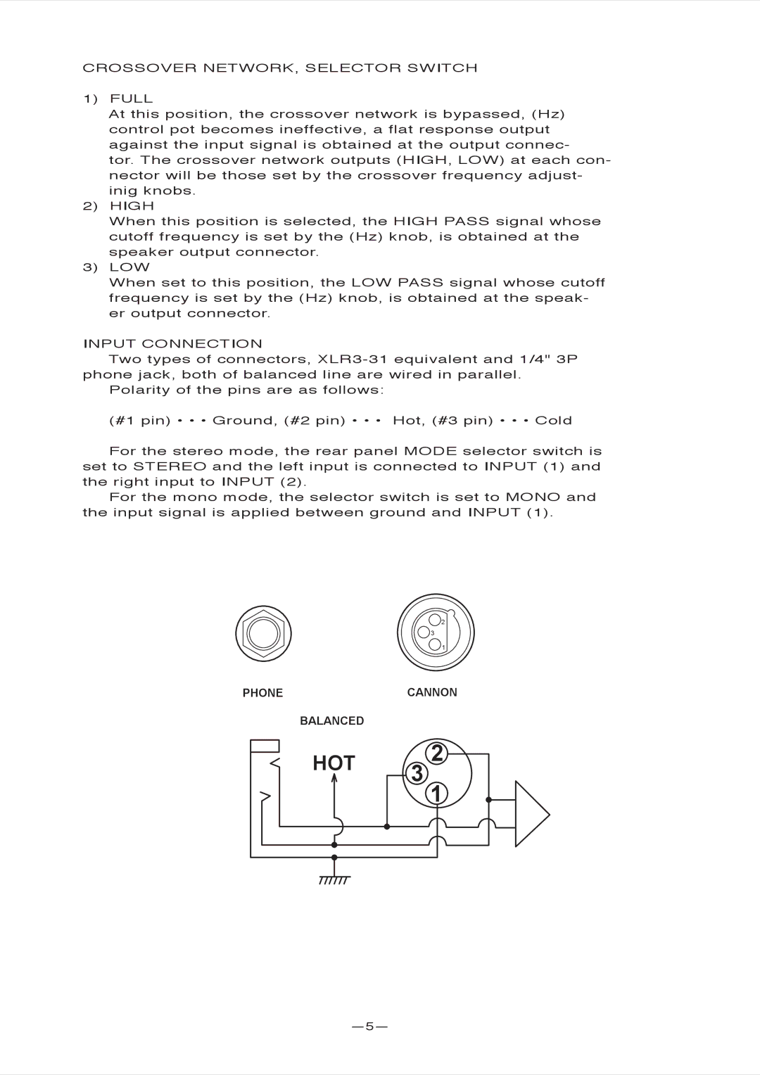
INPUT CONNECTION
Two types of connectors,
Polarity of the pins are as follows:
(#1 pin) • • • Ground, (#2 pin) • • • Hot, (#3 pin) • • • Cold
For the stereo mode, the rear panel MODE selector switch is set to STEREO and the left input is connected to INPUT (1) and the right input to INPUT (2).
For the mono mode, the selector switch is set to MONO and the input signal is applied between ground and INPUT (1).
2
3
1
PHONECANNON
BALANCED
HOT | 2 | |
3 1 | ||
|