CAUTION

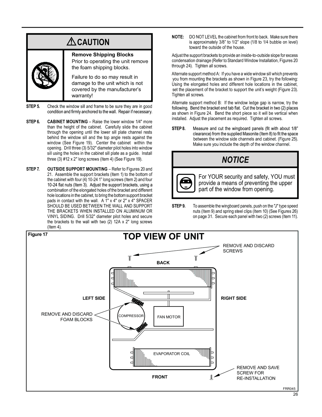
Remove Shipping Blocks

Prior to operating the unit remove the foam shipping blocks.

Failure to do so may result in damage to the unit which is not covered by the manufacturer’s warranty!

STEP 5. Check the window sill and frame to be sure they are in good

STEP 6. CABINET MOUNTING – Raise the lower window 1/4" more than the height of the cabinet. Carefully slide the cabinet through the opening until the lower sill plate channel rests behind the window sill and the top angle rests against the window (See Figure 19). Center the cabinet within the opening. Drill three (3) 5/32" diameter pilot holes into window sill using the holes in the cabinet sill plate as a guide. Install three (3) #12 x 2" long screws (Item 4) (See Figure 19).

STEP 7. OUTSIDE SUPPORT MOUNTING – Refer to Figures 20 and

21.Assemble the support brackets (Item 1) to the bottom of the cabinet with four (4) 10-24 1” long screws (Item 2) and four

combination of the elongated holes of the bracket and different hole locations in the cabinet, to bring the bottom support bracket pads in contact with the wall. A 1" x 4" or 2" x 4" SPACER SHOULD BE USED BETWEEN THE WALL AND SUPPORT THE BRACKETS WHEN INSTALLED ON ALUMINUM OR VINYL SIDING. Drill 5/32" diameter pilot holes and secure the brackets to the wall with two (2) 12A x 2" long screws (Item 4).

NOTE: DO NOT LEVEL the cabinet from front to back. Make sure there is approximately 3/8” to 1/2” slope (1/8 to 1/4 bubble on level) toward the outside of the house.

Adjust the support brackets to provide an inside-to-outside slope for excess condensation drainage (Refer to Standard Window Installation, Figures 20 through 24). Tighten all screws.

Alternate support method A: If you have a wide window sill which prevents you from mounting the brackets as shown in Figure 23, try the following: Using the elongated holes and different hole locations in the cabinet, set the placement of the bracket to support the unit’s weight (Figure 23). Tighten all screws.

Alternate support method B: If the window ledge gap is narrow, try the

as shown in Figure 24. Bend the short piece so it will be vertical when installed. Adjust the placement as required. Tighten all screws.

STEP 8.

between the window side channels and cabinet. (Figure 25). Make sure you include the depth of the window channel.

NOTICE

For YOUR security and safety, YOU must provide a means of preventing the upper part of the window from opening.

STEP 9. To assemble the wingboard panels, push on the "J" type speed nuts (Item 9) and spring steel clips (Item 10) (See Figures 26) on page 31. Secure each panel with two (2) screws (Item 11).

Figure 17

TOP VIEW OF UNIT

REMOVE AND DISCARD

SCREWS

BACK

LEFT SIDE

REMOVE AND DISCARD

COMPRESSOR

FAN MOTOR

FOAM BLOCKS


EVAPORATOR COIL

FRONT

RIGHT SIDE

REMOVE AND SAVE

SCREW FOR

RE-INSTALLATION

FRR045

26

Page 26
Image 26
Friedrich SL 24, SS15, SM15, SL 22, YS10 operation manual TOP View of Unit

SM15, SL 24, SS15, SL 22, YS10 specifications

The Friedrich YS10, SL 22, SS15, SL 24, and SM15 are a series of innovative machines designed for various industrial applications, primarily focusing on precision and efficiency in manufacturing processes. Each model boasts unique features tailored to meet distinct needs across different sectors.

The YS10 stands out with its advanced automation capabilities, enabling enhanced productivity through smart technology integration. It employs a state-of-the-art control system that allows operators to program complex tasks with ease, making it suitable for high-volume production environments. Additionally, the YS10 is equipped with an intuitive user interface that simplifies operation and minimizes training time for new users.

Moving on to the SL 22, this model is recognized for its versatility in handling diverse materials. It incorporates adjustable settings that allow users to switch between various manufacturing processes seamlessly. The SL 22 is also designed for energy efficiency, utilizing cutting-edge motion control technology to reduce power consumption without compromising performance. Its robust construction ensures longevity and reliability, essential for demanding industrial applications.

The SS15 is engineered specifically for precision tasks, featuring high-resolution sensors that guarantee exceptional accuracy in measurements. This model excels in environments where tight tolerances are crucial, such as in electronics and automotive manufacturing. The SS15 also includes advanced software for real-time monitoring and adjustments, ensuring consistent results throughout the production cycle.

On the other hand, the SL 24 offers enhanced speed and throughput capabilities, making it ideal for fast-paced industries. Its high-performance motor system delivers rapid cycle times while maintaining stability and control. The SL 24's modular design allows for easy upgrades and expansions, enabling manufacturers to adapt to changing market demands effectively.

Lastly, the SM15 focuses on simplifying maintenance processes, featuring accessible components that minimize downtime during servicing. This model employs predictive maintenance algorithms that analyze performance data, alerting users to potential issues before they lead to failures. The SM15 is designed with user experience in mind, offering a balance of functionality and ease of use.

Together, the Friedrich YS10, SL 22, SS15, SL 24, and SM15 represent a comprehensive lineup of machinery built for modern industrial challenges. With their advanced features, these machines offer companies the tools they need to enhance productivity, ensure precision, and improve overall operational efficiency.