Friedrich SV10A10, SV12A10, SV08A10 manual Capillary Tube

Models: SV10A10 SV08A10 SV12A10

1 27
Download 27 pages 11.9 Kb
Page 10
Image 10

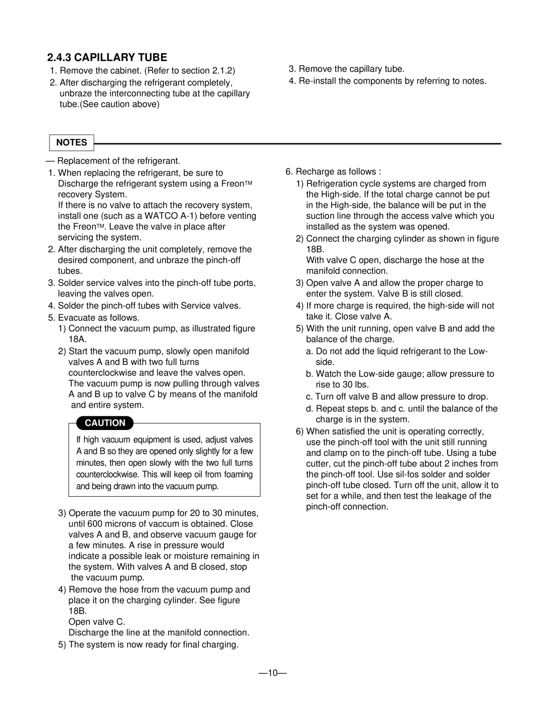
2.4.3 CAPILLARY TUBE

1.Remove the cabinet. (Refer to section 2.1.2)

2.After discharging the refrigerant completely, unbraze the interconnecting tube at the capillary tube.(See caution above)

NOTES

3.Remove the capillary tube.

4.Re-install the components by referring to notes.

Replacement of the refrigerant.

1.When replacing the refrigerant, be sure to Discharge the refrigerant system using a FreonTM recovery System.

If there is no valve to attach the recovery system, install one (such as a WATCO A-1) before venting the FreonTM. Leave the valve in place after servicing the system.

2.After discharging the unit completely, remove the desired component, and unbraze the pinch-off tubes.

3.Solder service valves into the pinch-off tube ports, leaving the valves open.

4.Solder the pinch-off tubes with Service valves.

5.Evacuate as follows.

1)Connect the vacuum pump, as illustrated figure 18A.

2)Start the vacuum pump, slowly open manifold valves A and B with two full turns counterclockwise and leave the valves open. The vacuum pump is now pulling through valves A and B up to valve C by means of the manifold and entire system.

CAUTION

If high vacuum equipment is used, adjust valves A and B so they are opened only slightly for a few minutes, then open slowly with the two full turns counterclockwise. This will keep oil from foaming and being drawn into the vacuum pump.

3)Operate the vacuum pump for 20 to 30 minutes, until 600 microns of vaccum is obtained. Close valves A and B, and observe vacuum gauge for a few minutes. A rise in pressure would indicate a possible leak or moisture remaining in the system. With valves A and B closed, stop the vacuum pump.

4)Remove the hose from the vacuum pump and place it on the charging cylinder. See figure 18B.

Open valve C.

Discharge the line at the manifold connection.

5)The system is now ready for final charging.

6.Recharge as follows :

1)Refrigeration cycle systems are charged from the High-side. If the total charge cannot be put in the High-side, the balance will be put in the suction line through the access valve which you installed as the system was opened.

2)Connect the charging cylinder as shown in figure 18B.

With valve C open, discharge the hose at the manifold connection.

3)Open valve A and allow the proper charge to enter the system. Valve B is still closed.

4)If more charge is required, the high-side will not take it. Close valve A.

5)With the unit running, open valve B and add the balance of the charge.

a.Do not add the liquid refrigerant to the Low- side.

b.Watch the Low-side gauge; allow pressure to rise to 30 lbs.

c.Turn off valve B and allow pressure to drop.

d.Repeat steps b. and c. until the balance of the charge is in the system.

6)When satisfied the unit is operating correctly, use the pinch-off tool with the unit still running and clamp on to the pinch-off tube. Using a tube cutter, cut the pinch-off tube about 2 inches from the pinch-off tool. Use sil-fos solder and solder pinch-off tube closed. Turn off the unit, allow it to set for a while, and then test the leakage of the pinch-off connection.

— 10—

Page 10
Image 10
Friedrich SV10A10, SV12A10, SV08A10 manual Capillary Tube

SV10A10, SV08A10, SV12A10 specifications

The Friedrich SV12A10, SV08A10, and SV10A10 are part of an advanced line of vertical machining centers designed for precision and efficiency in various industrial applications. Each model possesses distinct features and cutting-edge technologies, positioning them as ideal solutions for manufacturers seeking high-performance machinery.

The SV12A10 is characterized by its robust construction, offering a large working envelope that accommodates complex machining tasks. With a maximum spindle speed of 12,000 RPM, it enables efficient material removal and high surface finish quality. The machine is equipped with advanced linear guideways, providing smooth motion and reducing friction, which contributes to longer tool life and improved machining accuracy.

The SV08A10, on the other hand, is designed for compactness without compromising on performance. It combines a smaller footprint with high-speed capabilities, making it suitable for small to medium-sized workpieces. This model also incorporates a modern CNC control system that features user-friendly interfaces and powerful programming capabilities, streamlining operations and reducing setup times.

The SV10A10 strikes a balance between the two, offering a versatile solution that caters to diverse machining requirements. With a spindle speed of 10,000 RPM and a variety of optional attachments, it can handle a wide range of materials, from metals to plastics. Additionally, it features an automatic tool changer, which enhances productivity by minimizing downtime during tool swaps.

Common characteristics across these models include a rigid bed design that ensures stability during high-speed operations and thermal stability to mitigate expansion issues that could affect precision. All three models utilize advanced cooling systems that maintain optimal temperatures to preserve tool integrity and machining precision.

Moreover, these machines are equipped with integrated safety features, including emergency stop buttons and protective enclosures, ensuring a secure working environment. The CNC systems are also compatible with Industry 4.0 technologies, allowing for real-time monitoring and data analytics, which help optimize production processes.

In summary, the Friedrich SV12A10, SV08A10, and SV10A10 represent a range of machining solutions that blend precision engineering with innovative technology. Their versatility, high performance, and safety features make them excellent choices for manufacturers looking to enhance productivity and maintain high standards of quality in their operations.