2. IMPORTANT

INSTALLATION INSTRUCTIONS

Fan Cover Bracket

Exhaust Damper

Assembly

Tapping Screw

Figure 10

8 VENTILATION SYSTEM

(PREPARING OVEN FOR INSTALLATION)

(C)VERTICAL EXHAUST: OUTSIDE VENTILATION

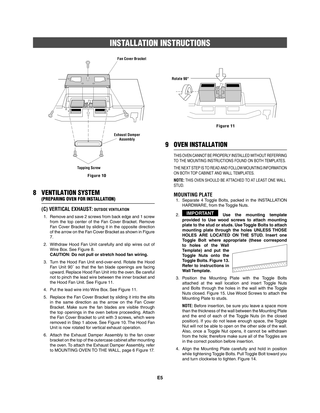
1.Remove and save 2 screws from back edge and 1 screw from the top center of the Fan Cover Bracket. Remove Fan Cover Bracket by sliding it in the opposite direction of the arrow on the Fan Cover Bracket as shown in Figure 7.

2.Withdraw Hood Fan Unit carefully and slip wires out of Wire Box. See Figure 8.

CAUTION: Do not pull or stretch hood fan wiring.

3.Turn the Hood Fan Unit end-over-end. Rotate the Hood Fan Unit 90˚ so that the fan blade openings are facing upward. Replace Hood Fan Unit into the oven. Be careful not to pinch the lead wire between the inner bracket and the Hood Fan Unit. See Figure 11.

4.Put the lead wire into Wire Box. See Figure 11.

5.Replace the Fan Cover Bracket by sliding it into the slits in the same direction as the arrow on the Fan Cover Bracket. Make sure the fan blades are visible through the top openings in the oven before proceeding. Attach the Fan Cover Bracket to unit with 3 screws, which were removed in Step 1 above. See Figure 10. The Hood Fan Unit is now rotated for vertical exhaust operation.

6.Attach the Exhaust Damper Assembly to the fan cover bracket on the top of the outercase cabinet after mounting the oven. To attach the Exhaust Damper Assembly, refer to MOUNTING OVEN TO THE WALL, page 6 Figure 17.

Rotate 90°

Figure 11

9 OVEN INSTALLATION

THIS OVEN CANNOT BE PROPERLY INSTALLED WITHOUT REFERRING TO THE MOUNTING INSTRUCTIONS FOUND ON BOTH TEMPLATES.

THE NEXT STEP IS TO READ AND FOLLOW MOUNTING INFORMATION ON BOTH TOP CABINET AND WALL TEMPLATES.

NOTE: THIS OVEN SHOULD BE ATTACHED TO AT LEAST ONE WALL STUD.

MOUNTING PLATE

1.Separate 4 Toggle Bolts, packed in the INSTALLATION HARDWARE, from the Toggle Nuts.

Use the mounting template provided to Use wood screws to attach mounting plate to the stud or studs. Use Toggle Bolts to attach mounting plate through the holes UNLESS THOSE HOLES ARE LOCATED ON THE STUD. Insert one Toggle Bolt where appropriate (these correspond to holes of the Wall

Template) and put the Toggle Nuts onto the Toggle Bolts. Figure 13. Refer to instructions in Wall Template.

3.Position the Mounting Plate with the Toggle Bolts attached at the wall location and insert Toggle Nuts and Bolts through the holes in the wall with the Toggle Nuts closed. Figure 15. Use Wood Screws to attach the Mounting Plate to studs.

NOTE: Before insertion, be sure you leave a space more than the thickness of the wall between the Mounting Plate and the end of each of the Toggle Nuts (in the closed position). If you do not leave enough space, the Toggle Nut will not be able to open on the other side of the wall. Also, once a Toggle Nut opens, it cannot be withdrawn from the hole; therefore make sure all of the Toggles are in the correct position before insertion.

4.Align the Mounting Plate carefully and hold in position while tightening Toggle Bolts. Pull Toggle Bolt toward you and turn clockwise to tighten. Figure 14.

E5

Page 5
Image 5
Frigidaire 316495062 installation instructions Oven Installation, Mounting Plate

316495062 specifications

The Frigidaire 316495062 is a vital component for consumers looking to boost the efficiency of their kitchen appliances. This high-performance range surface burner control switch is designed to provide both reliability and functionality in everyday cooking scenarios.

One of the standout features of the Frigidaire 316495062 is its robust design. Constructed with high-quality materials, it ensures longevity and durability, which is crucial for kitchen appliances that undergo daily use. This control switch has been meticulously engineered to be compatible with various Frigidaire models, making it a versatile option for many households. Its straightforward installation process allows users to replace malfunctioning switches with minimal effort, reducing the need for professional help.

In terms of technology, the Frigidaire 316495062 operates seamlessly, ensuring precise control over burner temperatures. This feature allows users to achieve their desired cooking outcomes consistently, be it simmering sauces or achieving a perfect sear on meats. The switch's design emphasizes user-friendliness, with clear markings that simplify the cooking process, making it ideal for both novice cooks and seasoned chefs.

The Frigidaire 316495062 also stands out for its energy efficiency. By providing effective control over heat levels, it contributes to reducing energy consumption in the kitchen. This attribute is increasingly important in today’s environmentally-conscious world, where consumers are looking to lower their energy bills while minimizing their carbon footprint.

Moreover, the ergonomic design of the switch ensures ease of use, allowing for quick adjustments even during high-pressure cooking situations. Its reliability under various cooking conditions makes it an indispensable part of Frigidaire’s reputation for quality and performance.

In conclusion, the Frigidaire 316495062 is not just a replacement part; it embodies the brand's commitment to innovation and user-centered design. Combining durability, ease of use, and energy efficiency, this control switch enhances the cooking experience, making it an essential addition for any Frigidaire-branded kitchen setup. Whether you're a cooking enthusiast or someone who values hassle-free meal preparation, the Frigidaire 316495062 is a smart choice to elevate your culinary adventures.