Manuals
/
Fujioh
/
Kitchen Appliance
/
Ventilation Hood
Fujioh
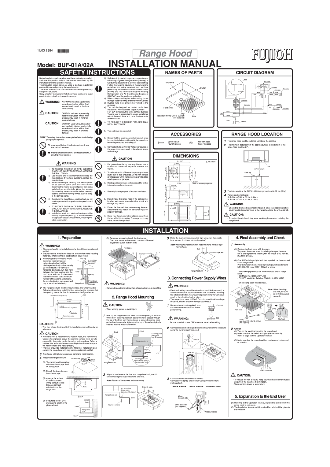
BUF-01A/02A
installation manual
Installation Manual, Range Hood, Safety Instructions, 1U03
Models:
BUF-01A/02A
1
1
2
2
Download
2 pages
32.35 Kb
1
2
Install
Dimension
Page 1
Image 1
Page 1
Page 2
Page 1
Image 1
Page 1
Page 2
Contents
SAFETY INSTRUCTIONS
INSTALLATION MANUAL
INSTALLATION
CIRCUIT DIAGRAM
ACCESSOIRES
MANUEL D’INSTALLATION
TAILLE ET DIMENSIONS
installé dans le tuyau
Top
Page
Image
Contents