ADJUSTING THE DIRECTION OF AIR CIRCULATION
Instructions relating to heating (*) are applicable only to “HEAT & COOL MODEL” (Reverse Cycle).
Vertical
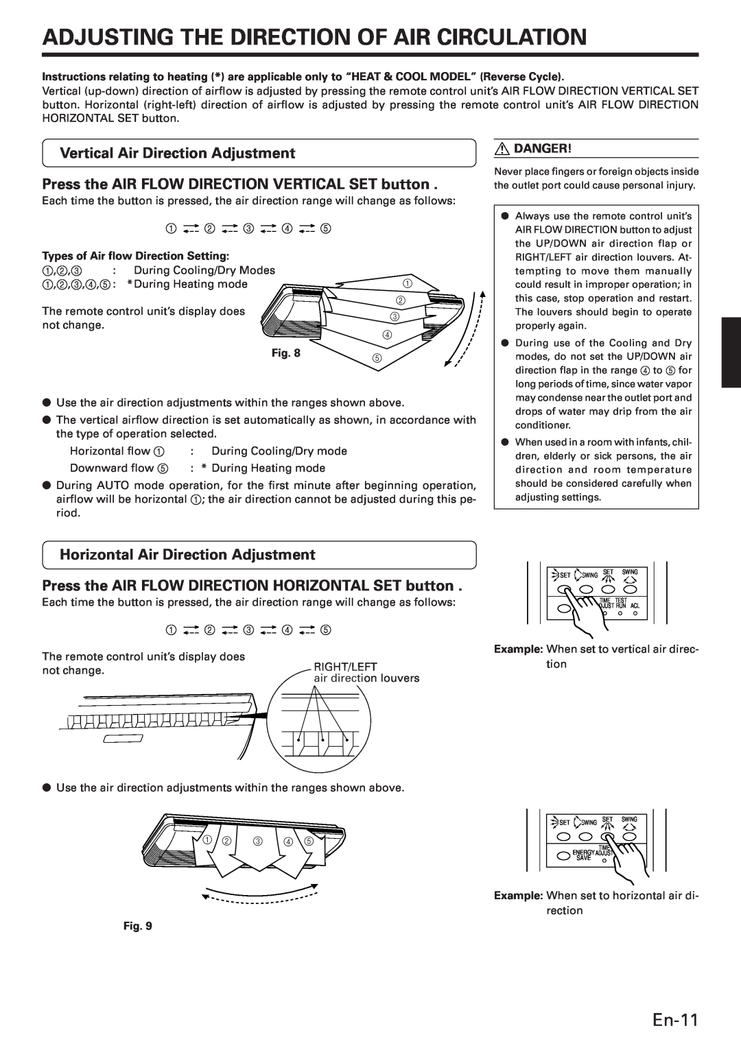
Vertical Air Direction Adjustment
Press the AIR FLOW DIRECTION VERTICAL SET button .
Each time the button is pressed, the air direction range will change as follows:
1 ![]()
![]() 2
2 ![]()
![]() 3
3 ![]()
![]() 4
4 ![]()
![]() 5
5
Types of Air flow Direction Setting:
1,2,3 : | During Cooling/Dry Modes |
|
1,2,3,4,5: | *During Heating mode | 1 |
2
The remote control unit’s display does |
| 3 |
not change. |
| |
| 4 | |
|
| |
| Fig. 8 | 5 |
|
|
●Use the air direction adjustments within the ranges shown above.
●The vertical airflow direction is set automatically as shown, in accordance with the type of operation selected.
Horizontal flow 1 : During Cooling/Dry mode
Downward flow 5 : * During Heating mode
●During AUTO mode operation, for the first minute after beginning operation, airflow will be horizontal 1; the air direction cannot be adjusted during this pe- riod.
![]() DANGER!
DANGER!
Never place fingers or foreign objects inside the outlet port could cause personal injury.
●Always use the remote control unit’s AIR FLOW DIRECTION button to adjust the UP/DOWN air direction flap or RIGHT/LEFT air direction louvers. At- tempting to move them manually could result in improper operation; in this case, stop operation and restart. The louvers should begin to operate properly again.
●During use of the Cooling and Dry modes, do not set the UP/DOWN air direction flap in the range 4 to 5 for long periods of time, since water vapor may condense near the outlet port and drops of water may drip from the air conditioner.
●When used in a room with infants, chil- dren, elderly or sick persons, the air direction and room temperature should be considered carefully when adjusting settings.
Horizontal Air Direction Adjustment
Press the AIR FLOW DIRECTION HORIZONTAL SET button .
Each time the button is pressed, the air direction range will change as follows:
1 ![]()
![]() 2
2 ![]()
![]() 3
3 ![]()
![]() 4
4 ![]()
![]() 5
5
The remote control unit’s display does |
|
| RIGHT/LEFT |
| ||
not change. |
|
|
| |||
|
| air direction louvers | ||||
|
|
| ||||
|
|
|
|
|
|
|
|
|
|
|
|
|
|
|
|
|
|
|
|
|
|
|
|
|
|
|
|
|
|
|
|
|
|
|
●Use the air direction adjustments within the ranges shown above.
1 2 3 4 5
![]()
![]() SET
SET ![]() SWING SET SWING
SWING SET SWING
TIME TEST
ENAGY ADJUST RUN ACL
SAVE
Example: When set to vertical air direc- tion
![]()
![]() SET
SET ![]() SWING SET SWING
SWING SET SWING
TIME TEST
ENERGYADJUST RUN ACL
SAVE
Example: When set to horizontal air di- rection
Fig. 9