L i f e B o o k B S e r i e s N o t e b o o k B I O S
Serial/Parallel Port Configurations Submenu of the Advanced Menu
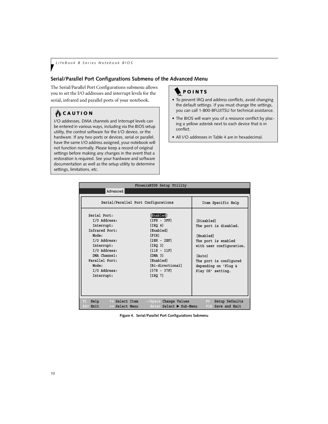
The Serial/Parallel Port Configurations submenu allows you to set the I/O addresses and interrupt levels for the
serial, infrared and parallel ports of your notebook.
 C A U T I O N
I/O addresses, DMA channels and Interrupt levels can be entered in various ways, including via the BIOS setup utility, the control software for the I/O device, or the hardware. If any two ports or devices, serial or parallel, have the same I/O address assigned, your notebook will not function normally. Please keep a record of original settings before making any changes in the event that a restoration is required. See your hardware and software documentation as well as the setup utility to determine settings, limitations, etc.
 P O I N T S
•To prevent IRQ and address conflicts, avoid changing the default settings. If you must change the settings, you can call
•The BIOS will warn you of a resource conflict by plac- ing a yellow asterisk next to each device that is in conflict.
•All I/O addresses in Table 4 are in hexadecimal.
PhoenixBIOS Setup Utility
Advanced
|
|
|
|
|
|
| Serial/Parallel Port Configurations | Item Specific Help |
| ||
|
|
|
|
| |
| Serial Port: | [Enabled] |
|
| |
| I/O Address: | [3F8 | - 3FF] | [Disabled] |
|
| Interrupt: | [IRQ 4] | The port is disabled. |
| |
| Infrared Port: | [Enabled] |
|
| |
| Mode: | [FIR] |
| [Enabled] |
|
| I/O Address: | [2E8 | - 2EF] | The port is enabled |
|
| Interrupt: | [IRQ 3] | with user configuration. |
| |
| I/O Address: | [118 | - 11F] |
|
|
| DMA Channel: | [DMA 3] | [Auto] |
| |
| Parallel Port: | [Enabled] | The port is configured |
| |
| Mode: | depending on 'Plug & |
| ||
| I/O Address: | [378 | - 37F] | Play OS' setting. |
|
| Interrupt: | [IRQ 7] |
|
| |
|
|
|
|
|
|
|
|
|
|
|
|
F1 Help | Select | Item |
ESC Exit | Select | Menu |
Change | Values | |
Enter | Select | ▲ |
F9 Setup Defaults
F10 Save and Exit
Figure 4. Serial/Parallel Port Configurations Submenu
10
