DCU105 3 specifications
The Fujitsu DCU105 3 is a cutting-edge data center management unit designed to optimize the performance and efficiency of IT environments. As data centers continue to grow in complexity, the need for robust management solutions becomes increasingly critical. The DCU105 3 addresses these challenges through a combination of advanced features, innovative technologies, and user-friendly characteristics.One of the standout features of the DCU105 3 is its ability to consolidate management of various data center resources. This unit provides a centralized dashboard that offers real-time monitoring and control over critical systems such as power, cooling, and network management. By streamlining these processes, the DCU105 3 enhances overall operational efficiency and minimizes the risk of downtimes due to system failures.
Equipped with advanced telemetry capabilities, the Fujitsu DCU105 3 utilizes sensors to collect data on temperature, humidity, and energy consumption. This data is crucial for maintaining optimal environmental conditions, ensuring that servers and other critical hardware operate within safe parameters. Additionally, with built-in analytics tools, users can gain insights into historical trends and performance metrics, facilitating informed decision-making.
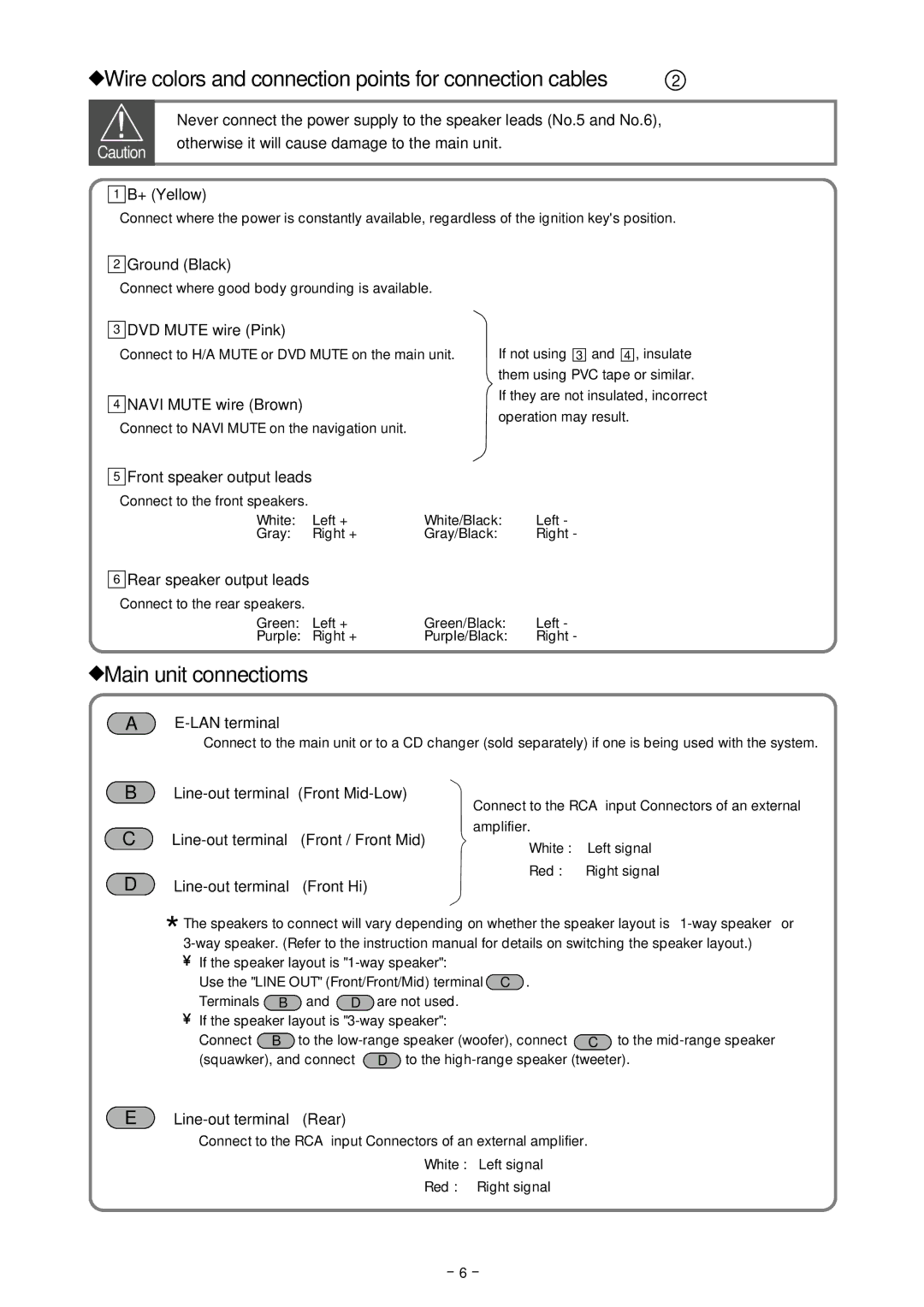
The DCU105 3 also excels in connectivity options, featuring multiple interfaces such as Ethernet, RS-232, and USB ports. This flexibility allows for seamless integration with existing IT infrastructure and simplifies the deployment process. Furthermore, the device supports standard protocols, making it compatible with various software applications, which aids in simplifying operations while reducing complexity.
In terms of energy efficiency, the Fujitsu DCU105 3 adopts cutting-edge technologies that promote sustainability. Its intelligent power management system optimizes power distribution to reduce energy consumption while ensuring all components receive adequate power. This focus on energy efficiency not only helps to lower operational costs but also supports organizations in meeting sustainability goals.
Security is another critical aspect of the DCU105 3. Fujitsu has incorporated advanced security features that protect sensitive data and operations from unauthorized access. This includes support for encrypted communications and robust authentication mechanisms, ensuring that only authorized personnel can interact with critical management features.
In summary, the Fujitsu DCU105 3 represents a significant advancement in data center management technology. With its comprehensive monitoring capabilities, intelligent energy management, flexible connectivity, and robust security features, it is well-equipped to meet the demands of modern data centers. Organizations looking to enhance their data center operations will find the DCU105 3 to be an invaluable asset, driving efficiency and contributing to a more sustainable future.

