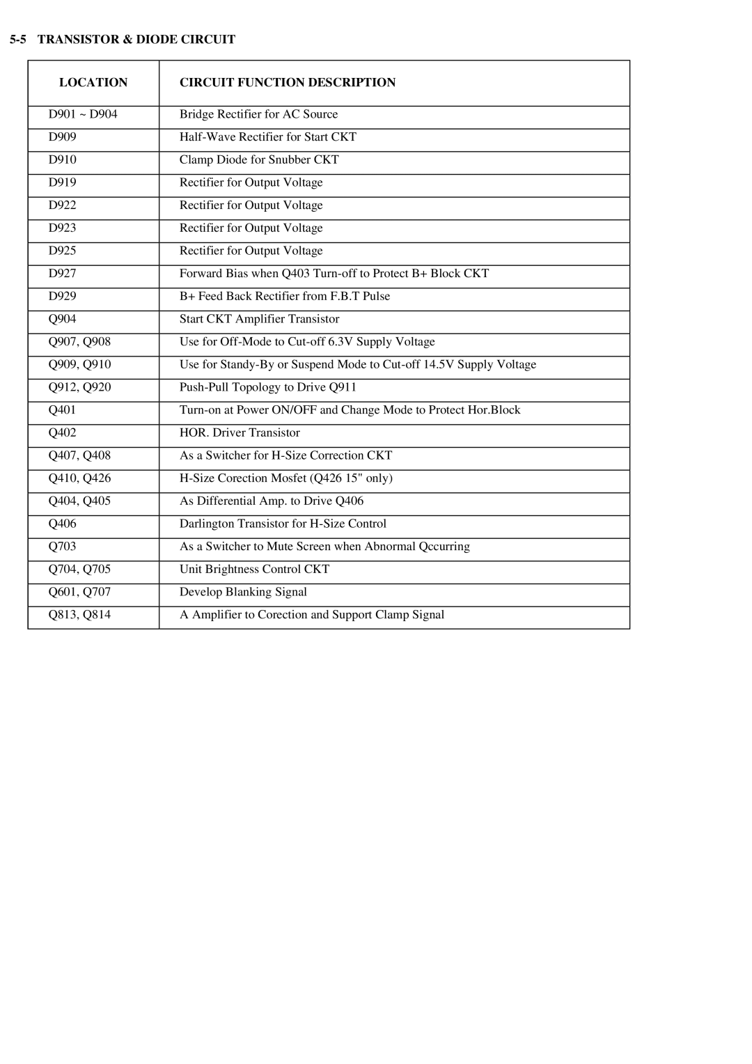
LOCATION | CIRCUIT FUNCTION DESCRIPTION |
D901 ~ D904 | Bridge Rectifier for AC Source |
D909 | |
D910 | Clamp Diode for Snubber CKT |
D919 | Rectifier for Output Voltage |
D922 | Rectifier for Output Voltage |
D923 | Rectifier for Output Voltage |
D925 | Rectifier for Output Voltage |
D927 | Forward Bias when Q403 |
D929 | B+ Feed Back Rectifier from F.B.T Pulse |
Q904 | Start CKT Amplifier Transistor |
Q907, Q908 | Use for |
Q909, Q910 | Use for |
Q912, Q920 | |
Q401 | |
Q402 | HOR. Driver Transistor |
Q407, Q408 | As a Switcher for |
Q410, Q426 | |
Q404, Q405 | As Differential Amp. to Drive Q406 |
Q406 | Darlington Transistor for |
Q703 | As a Switcher to Mute Screen when Abnormal Qccurring |
Q704, Q705 | Unit Brightness Control CKT |
Q601, Q707 | Develop Blanking Signal |
Q813, Q814 | A Amplifier to Corection and Support Clamp Signal |