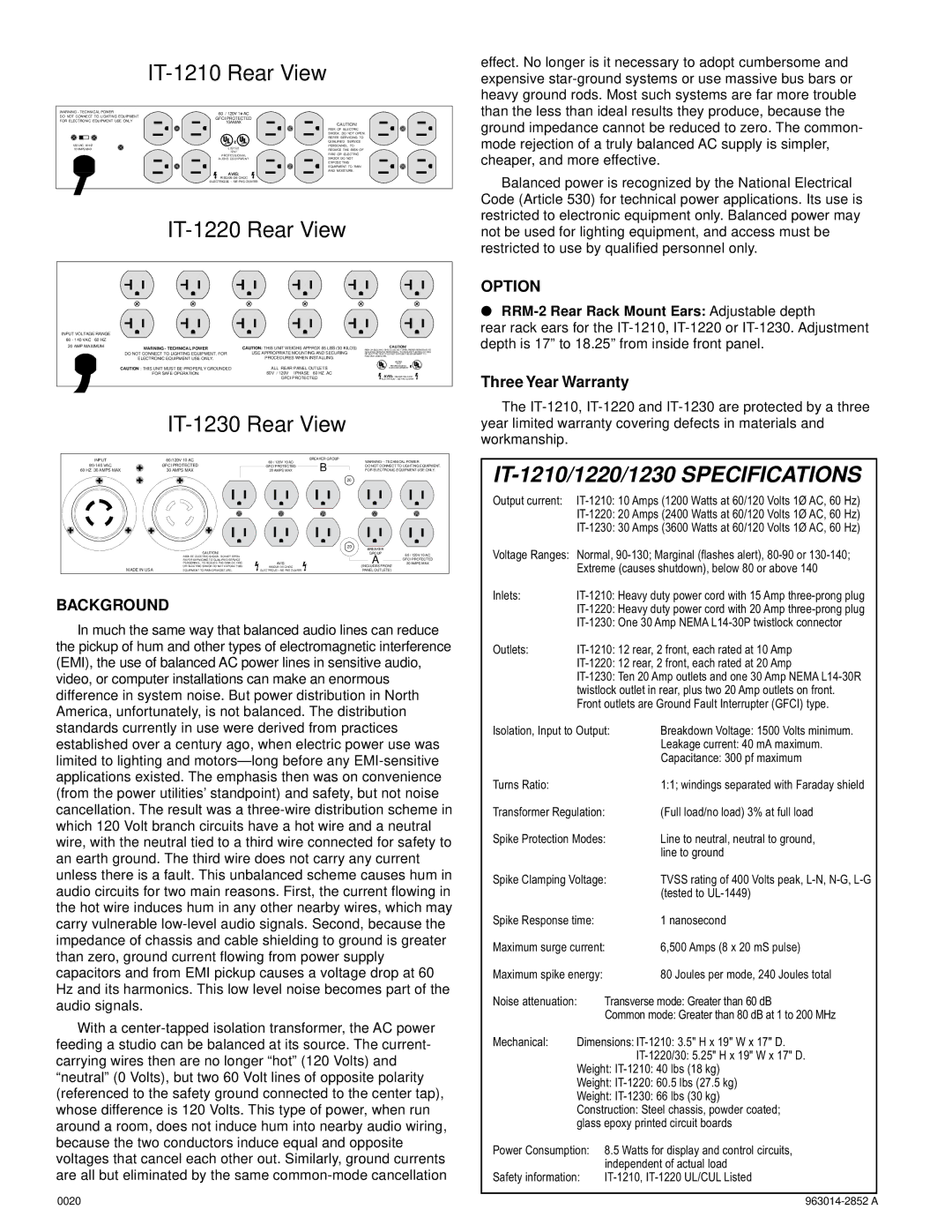
IT-1210 Rear View
WARNING - TECHNICAL POWER | 60 / 120V 1 AC | |
DO NOT CONNECT TO LIGHTING EQUIPMENT | GFCI PROTECTED | |
FOR ELECTRONIC EQUIPMENT USE ONLY | |
| 10A MAX | CAUTION! |
| | |
| | | RISK OF ELECTRIC |
| | | SHOCK. DO NOT OPEN. |
| | | REFER SERVICING TO |
| Æ | Æ | QUALIFIED SERVICE |
120 VAC 60 HZ | PERSONNEL. TO |
10 AMPS MAX | | LISTED | REDUCE THE RISK OF |
| | 7Z37 | FIRE OR ELECTRIC |
| PROFESSIONAL |
| AUDIO EQUIPMENT | SHOCK DO NOT |
| | | EXPOSE THIS |
| | | EQUIPMENT TO RAIN |
| | AVIS: | AND MOISTURE. |
| | |
| RISQUE DE CHOC | |
| ELECTRIQUE -- NE PAS OUVRIR | |
IT-1220 Rear View
INPUT VOLTAGE RANGE | | | |
80 - 140 VAC 60 HZ | | | |
20 AMP MAXIMUM | WARNING - TECHNICAL POWER | CAUTION: THIS UNIT WEIGHS APPROX 65 LBS (30 KILOS) | CAUTION! |
| RISK OF ELECTRIC SHOCK. DO NOT OPEN. REFER SERVICING TO |
| DO NOT CONNECT TO LIGHTING EQUIPMENT. FOR | USE APPROPRIATE MOUNTING AND SECURING | QUALIFIED SERVICE PERSONNEL. TO REDUCE THE RISK OF FIRE |
| OR ELECTRIC SHOCK DO NOT EXPOSE THIS EQUIPMENT TO |
| PROCEDURES WHEN INSTALLING. | RAIN AND MOISTURE. |
| ELECTRONIC EQUIPMENT USE ONLY. | LISTED |
| | | 7Z37 |
| CAUTION : THIS UNIT MUST BE PROPERLY GROUNDED | ALL REAR PANEL OUTLETS | PROFESSIONAL |
| ® AUDIO EQUIPMENT ® |
| FOR SAFE OPERATION. | 60V / 120V 1PHASE 60 HZ AC | AVIS: RISQUE DE CHOC |
| | GFCI PROTECTED |
| | ELECTRIQUE -- NE PAS OUVRIR |
IT-1230 Rear View
| INPUT | 60/120V 10 AC | 60 / 120V 10 AC | BREAKER GROUP | WARNING— TECHNICAL POWER |
| B |
| 80-140 VAC | GFCI PROTECTED | GFCI PROTECTED | DO NOT CONNECT TO LIGHTING EQUIPMENT. |
| 60 HZ 30 AMPS MAX | 30 AMPS MAX | 20 AMPS MAX | FOR ELECTRONIC EQUIPMENT USE ONLY. |
| | | | | 20 |
| | | 20 | |
| | | BREAKER | |
| CAUTION! | | GROUP | 60 / 120V 10 AC |
| RISK OF ELECTRIC SHOCK. DO NOT OPEN. | | A |
| REFER SERVICING TO QUALIFIED SERVICE | | GFCI PROTECTED |
| PERSONNEL. TO REDUCE THE RISK OF FIRE | AVIS: | 20 AMPS MAX |
MADE IN USA | OR ELECTRIC SHOCK DO NOT EXPOSE THIS | RISQUE DE CHOC | (INCLUDES FRONT | |
EQUIPMENT TO RAIN OR MOISTURE. | ELECTRIQUE—NE PAS OUVRIR | PANEL OUTLETS) | |
BACKGROUND
In much the same way that balanced audio lines can reduce the pickup of hum and other types of electromagnetic interference (EMI), the use of balanced AC power lines in sensitive audio, video, or computer installations can make an enormous difference in system noise. But power distribution in North America, unfortunately, is not balanced. The distribution standards currently in use were derived from practices established over a century ago, when electric power use was limited to lighting and motors—long before any EMI-sensitive applications existed. The emphasis then was on convenience (from the power utilities’ standpoint) and safety, but not noise cancellation. The result was a three-wire distribution scheme in which 120 Volt branch circuits have a hot wire and a neutral wire, with the neutral tied to a third wire connected for safety to an earth ground. The third wire does not carry any current unless there is a fault. This unbalanced scheme causes hum in audio circuits for two main reasons. First, the current flowing in the hot wire induces hum in any other nearby wires, which may carry vulnerable low-level audio signals. Second, because the impedance of chassis and cable shielding to ground is greater than zero, ground current flowing from power supply capacitors and from EMI pickup causes a voltage drop at 60 Hz and its harmonics. This low level noise becomes part of the audio signals.
With a center-tapped isolation transformer, the AC power feeding a studio can be balanced at its source. The current- carrying wires then are no longer “hot” (120 Volts) and “neutral” (0 Volts), but two 60 Volt lines of opposite polarity (referenced to the safety ground connected to the center tap), whose difference is 120 Volts. This type of power, when run around a room, does not induce hum into nearby audio wiring, because the two conductors induce equal and opposite voltages that cancel each other out. Similarly, ground currents are all but eliminated by the same common-mode cancellation
effect. No longer is it necessary to adopt cumbersome and expensive star-ground systems or use massive bus bars or heavy ground rods. Most such systems are far more trouble than the less than ideal results they produce, because the ground impedance cannot be reduced to zero. The common- mode rejection of a truly balanced AC supply is simpler, cheaper, and more effective.
Balanced power is recognized by the National Electrical Code (Article 530) for technical power applications. Its use is restricted to electronic equipment only. Balanced power may not be used for lighting equipment, and access must be restricted to use by qualified personnel only.
OPTION
●RRM-2 Rear Rack Mount Ears: Adjustable depth
rear rack ears for the IT-1210, IT-1220 or IT-1230. Adjustment depth is 17” to 18.25” from inside front panel.
Three Year Warranty
The IT-1210, IT-1220 and IT-1230 are protected by a three year limited warranty covering defects in materials and workmanship.
IT-1210/1220/1230 SPECIFICATIONS
Output current: IT-1210: 10 Amps (1200 Watts at 60/120 Volts 1¯ AC, 60 Hz) IT-1220: 20 Amps (2400 Watts at 60/120 Volts 1¯ AC, 60 Hz) IT-1230: 30 Amps (3600 Watts at 60/120 Volts 1¯ AC, 60 Hz)
Voltage Ranges: Normal, 90-130; Marginal (flashes alert), 80-90 or 130-140; Extreme (causes shutdown), below 80 or above 140
Inlets: | IT-1210: Heavy duty power cord with 15 Amp three-prong plug |
| IT-1220: Heavy duty power cord with 20 Amp three-prong plug |
| IT-1230: One 30 Amp NEMA L14-30P twistlock connector |
Outlets: | IT-1210: 12 rear, 2 front, each rated at 10 Amp |
| IT-1220: 12 rear, 2 front, each rated at 20 Amp |
| IT-1230: Ten 20 Amp outlets and one 30 Amp NEMA L14-30R |
| twistlock outlet in rear, plus two 20 Amp outlets on front. |
| Front outlets are Ground Fault Interrupter (GFCI) type. |
Isolation, Input to Output: | Breakdown Voltage: 1500 Volts minimum. |
| | Leakage current: 40 mA maximum. |
| | Capacitance: 300 pf maximum |
Turns Ratio: | | 1:1; windings separated with Faraday shield |
Transformer Regulation: | (Full load/no load) 3% at full load |
Spike Protection Modes: | Line to neutral, neutral to ground, |
| | line to ground |
Spike Clamping Voltage: | TVSS rating of 400 Volts peak, L-N, N-G, L-G |
| | (tested to UL-1449) |
Spike Response time: | 1 nanosecond |
Maximum surge current: | 6,500 Amps (8 x 20 mS pulse) |
Maximum spike energy: | 80 Joules per mode, 240 Joules total |
Noise attenuation: | Transverse mode: Greater than 60 dB |
| | Common mode: Greater than 80 dB at 1 to 200 MHz |
Mechanical: | Dimensions: IT-1210: 3.5" H x 19" W x 17" D. |
| | IT-1220/30: 5.25" H x 19" W x 17" D. |
| Weight: IT-1210: 40 lbs (18 kg) |
| Weight: IT-1220: 60.5 lbs (27.5 kg) |
| Weight: IT-1230: 66 lbs (30 kg) |
| Construction: Steel chassis, powder coated; |
| glass epoxy printed circuit boards |
Power Consumption: | 8.5 Watts for display and control circuits, |
| | independent of actual load |
Safety information: | IT-1210, IT-1220 UL/CUL Listed |