Enclosure Construction
All enclosures should be constructed from 18mm (3/4”) Medium Density Fibre board. Enclosures should be glued and screwed, because MDF is porous. FUSION recommends sealing the internal sides with a polyurethane sealer prior to installation. To accurately cut the subwoofer hole use the unique FUSION ruler guide included inside the FUSION Sub- woofer packaging.
Enclosure Placement
An important factor is to place the subwoofer enclosure as far back in the vehicle as possible, so that the natural bass gain of the vehicle is utilised. If your vehicle is a hatch back, always experiment with which direction the subwoofer is fac- ing. Facing the subwoofer towards the rear of the car, should enhance the low down bass that PowerPlant Subwoofers are designed to produce.
Enclosure Tuning
When tuning the system it is always a good idea to try running the subwoofer out of phase (which means switching the speaker wires around) with your other speakers. Do this and listen to the system to see if the perception of bass is more from the subwoofer location or the front speaker location. Which ever way gives the better perception that the bass is coming from the front speakers, would quite safely guarantee the subwoofer is wired correctly.
Calculating Enclosure ‘Box’ Volume
Cuft:
To calculate Cuft multiply the height (A), width (B), depth (C) in inches, then divide that number by 1728. Example: 10” high x 18” wide x 12” deep = 2160 inches³
Divide 2160/1728 = 1.25 ft³
Litres:
To calculate Litres, multiply the height (A), width (B), depth (C) in centimetres, then divide that number by 1000. Example: 25.4cm high x 45.72cm wide x 30.48cm deep = 3539cm³
Divide 35396/1000 = 35.39 litres
Tech Tips
TOTAL AMPERAGE | 10 | |||||||
0 – 20 | 14 | 12 | 12 | 10 | 10 | 8 | 8 | 8 |
20 – 35 | 12 | 10 | 8 | 8 | 6 | 6 | 6 | 4 |
35 – 50 | 10 | 8 | 8 | 6 | 4 | 4 | 4 | 4 |
50 – 65 | 8 | 8 | 6 | 4 | 4 | 4 | 4 | 2 |
65 – 85 | 6 | 6 | 4 | 4 | 2 | 2 | 2 | 0 |
85 – 105 | 6 | 6 | 4 | 2 | 2 | 2 | 2 | 0 |
105 | 4 | 4 | 4 | 2 | 0 | 0 | 0 | 0 |
125 | 2 | 2 | 2 | 0 | 0 | 0 | 0 | 0 |
The above chart shows cable gauges to be used, if no less than a 0.5 volt drop is acceptable. If aluminium wire or tinned wired is used, the gauges should be of an even larger size to compensate. Cable gauge size calculation takes into account terminal connection resistance.
Ohms Law Simplified
| IR | E |
|
| ||
| I |
|
| |||
| W |
| E2 |
| ||
| I |
|
| W |
| |
WR | voltage |
| resistance | W | ||
E | I | 2 | ||||
|
| R |
| |||
E |
| I | W | E2 | ||
| currenamperage | s |
|
| ||
R | watt | R | ||||
t | ||||||
| W |
|
| I2R |
| |
| E |
|
|
| ||
|
|
|
|
| ||
| W/R | EI |
|
| ||
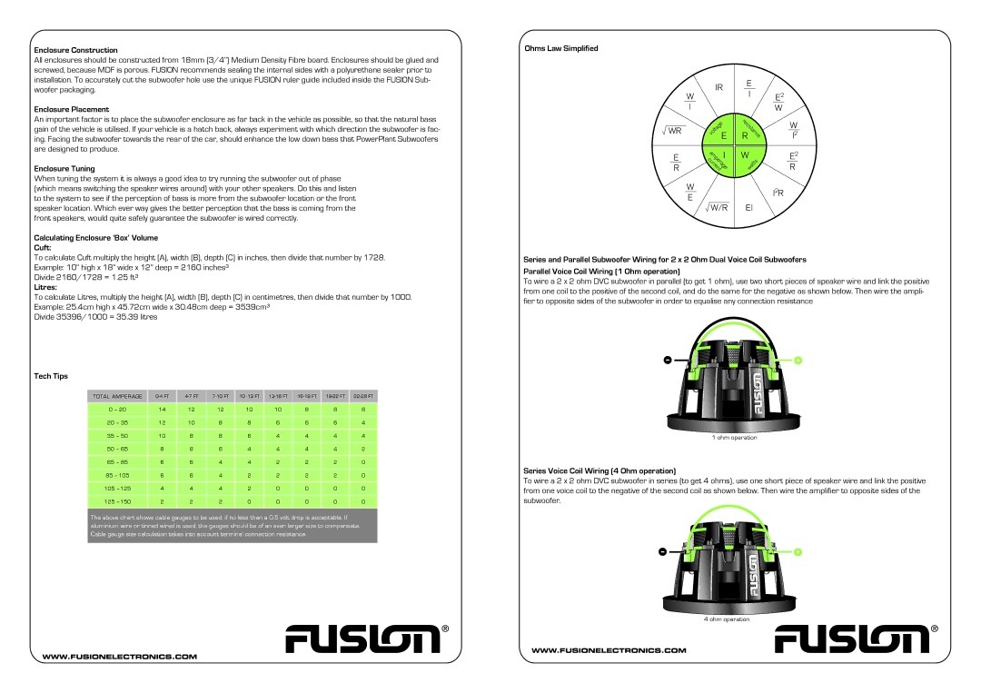
Series and Parallel Subwoofer Wiring for 2 x 2 Ohm Dual Voice Coil Subwoofers
Parallel Voice Coil Wiring (1 Ohm operation)
To wire a 2 x 2 ohm DVC subwoofer in parallel (to get 1 ohm), use two short pieces of speaker wire and link the positive from one coil to the positive of the second coil, and do the same for the negative as shown below. Then wire the ampli- fier to opposite sides of the subwoofer in order to equalise any connection resistance
-![]()
![]()
![]()
![]()
![]()
![]()
![]()
![]()
![]() +
+
1 ohm operation
Series Voice Coil Wiring (4 Ohm operation)
To wire a 2 x 2 ohm DVC subwoofer in series (to get 4 ohms), use one short piece of speaker wire and link the positive from one voice coil to the negative of the second coil as shown below. Then wire the amplifier to opposite sides of the subwoofer.
-![]()
![]()
![]()
![]()
![]()
![]()
![]()
![]()
![]() +
+
4 ohm operation