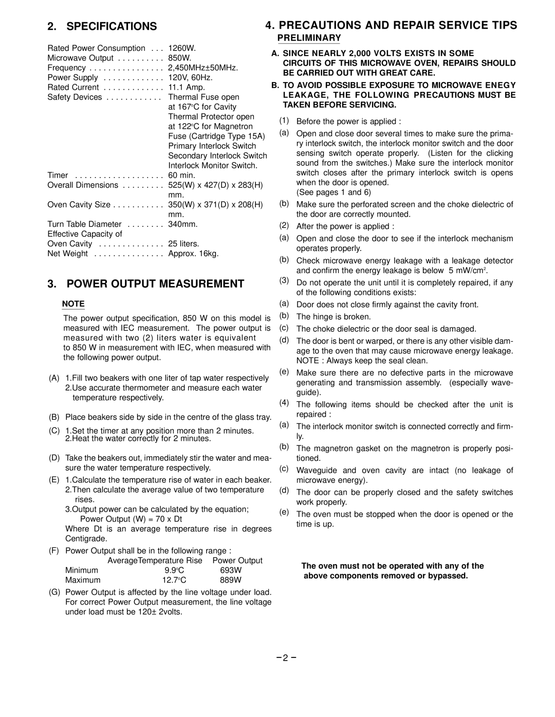
EM-S85 specifications
The Garland EM-S85 is an advanced electric meat slicer designed for both commercial and home kitchens, providing users with precision and efficiency. This machine stands out with its robust build and user-friendly features, making it an ideal choice for delis, restaurants, and catering services.One of the main features of the Garland EM-S85 is its powerful motor. This machine is equipped with a high-torque motor that ensures consistent slicing through various types of meat, cheese, and vegetables. The motor's efficiency enables it to handle both large and smaller quantities without overheating, ensuring reliability during busy periods.
The blade of the EM-S85 is another highlight of its design. This slicer features a durable, stainless-steel blade that maintains sharpness over time, ensuring clean and precise cuts. The blade is adjustable, allowing users to select the desired thickness of slices, which is perfect for customizing portions for different recipes or presentations. This adaptability enhances the machine's versatility, making it suitable for various applications from thinly sliced deli meats to thicker cuts for sandwiches or charcuterie boards.
Safety is a priority with the Garland EM-S85. It comes equipped with a number of safety features, including a safety guard that protects users from accidental contact with the blade. The non-slip feet provide stability during operation, further minimizing risks. Additionally, the machine is designed for easy cleaning, with removable parts that facilitate thorough maintenance after use.
The EM-S85 also incorporates advanced technology that promotes efficiency and ease of use. It features an integrated power switch for quick access and operation. Its lightweight construction allows for easy maneuverability, enabling users to position it conveniently in their workspace.
Moreover, the Garland EM-S85 showcases a sleek, modern design that not only complements any kitchen decor but also signifies its professional quality. The machine's thoughtful engineering and robust performance make it a valuable addition to any food preparation environment, whether commercial or domestic.
In conclusion, the Garland EM-S85 electric meat slicer combines powerful performance with user-friendly features and safety in mind. With its adjustable blade, robust motor, and innovative design, it caters to the needs of chefs and home cooks alike, demonstrating reliability and versatility in meat slicing. Its commitment to quality ensures that users achieve perfect slices every time, elevating their culinary experience.

