3)Gently pry the old microcontroller from the socket, and insert the new PIC16F688.
4)Finally, the 12V DC power adapter will need to be replaced. WARNING: the 12V power adapter which shipped with the
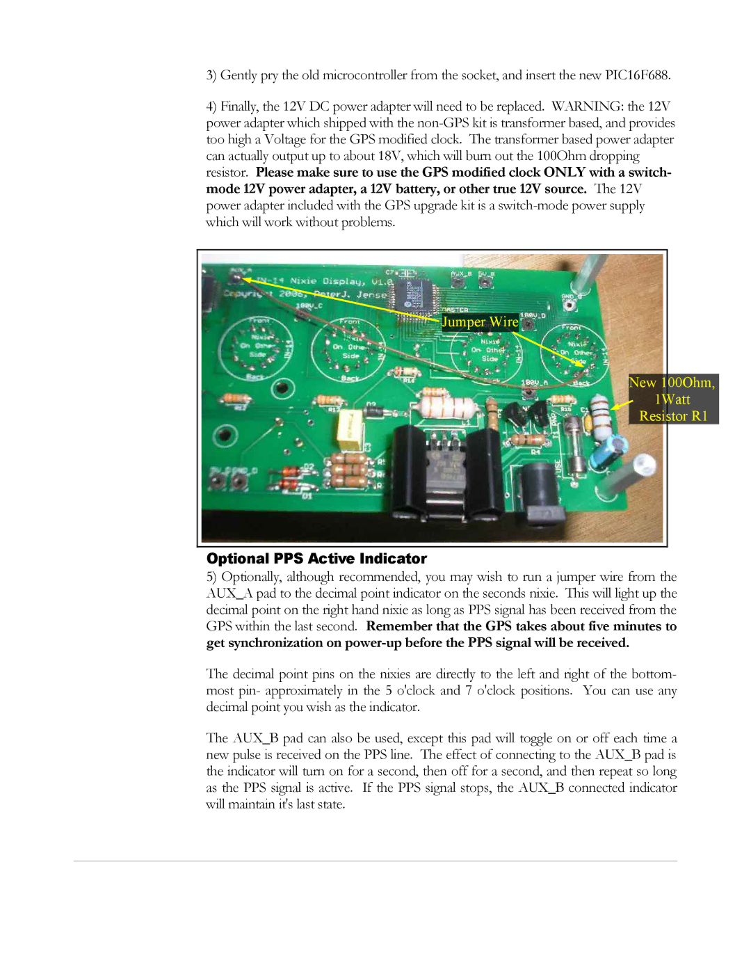
![]() Jumper Wire
Jumper Wire
New 100Ohm,
1Watt
Resistor R1
Optional PPS Active Indicator
5)Optionally, although recommended, you may wish to run a jumper wire from the AUX_A pad to the decimal point indicator on the seconds nixie. This will light up the decimal point on the right hand nixie as long as PPS signal has been received from the GPS within the last second. Remember that the GPS takes about five minutes to get synchronization on
The decimal point pins on the nixies are directly to the left and right of the bottom- most pin- approximately in the 5 o'clock and 7 o'clock positions. You can use any decimal point you wish as the indicator.
The AUX_B pad can also be used, except this pad will toggle on or off each time a new pulse is received on the PPS line. The effect of connecting to the AUX_B pad is the indicator will turn on for a second, then off for a second, and then repeat so long as the PPS signal is active. If the PPS signal stops, the AUX_B connected indicator will maintain it's last state.