250D and 2250D
GENERAL
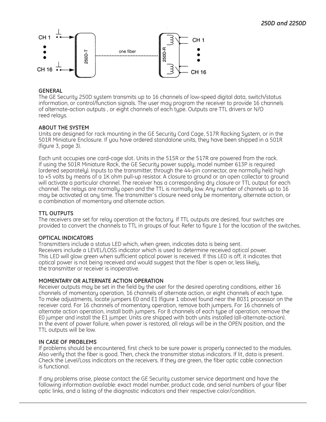
The GE Security 250D system transmits up to 16 channels of
reed relays.
ABOUT THE SYSTEM
Units are designed for rack mounting in the GE Security Card Cage, 517R Racking System, or in the 501R Miniature Enclosure. If you have ordered standalone units, they have been shipped in a 501R (figure 3, page 3).
Each unit occupies one
TTL OUTPUTS
The receivers are set for relay operation at the factory. If TTL outputs are desired, four switches are provided to convert the channels to TTL in groups of four. Refer to figure 1 for the location of the switches.
OPTICAL INDICATORS
Transmitters include a status LED which, when green, indicates data is being sent. Receivers include a LEVEL/LOSS indicator which is used to determine received optical power.
This LED will glow green when sufficient optical power is received. If this LED is off, it indicates that optical power is not being received and would suggest that the fiber is open or, less likely,
the transmitter or receiver is inoperative.
MOMENTARY OR ALTERNATE ACTION OPERATION
Receiver outputs may be set in the field by the user for the desired operating conditions, either 16 channels of momentary operation, 16 channels of alternate action, or eight channels of each type.
To make adjustments, locate jumpers E0 and E1 (figure 1 above) found near the 8031 processor on the receiver card. For 16 channels of momentary operation, remove both jumpers. For 16 channels of alternate action operation, install both jumpers. For 8 channels of each type of operation, remove the E0 jumper and install the E1 jumper. Units are shipped with both units installed
IN CASE OF PROBLEMS
If problems should be encountered, first check to be sure power is properly connected to the modules. Also verify that the fiber is good. Then, check the transmitter status indicators. If lit, data is present. Check the Level/Loss indicators on the receivers. If they are green, the fiber optic cable connection
is functional.
If any problems arise, please contact the GE Security customer service department and have the following information available: exact model number, product code, and serial numbers of your fiber optic links, and a listing of the diagnostic indicators and their respective color/condition.