STORING A REDIAL NUMBER
1.Repeat steps 1 through 6 in Storing a Name and Number in Memory.
2.Press the REDIAL button.
3.Press the MEMORY button to store the number. You will hear a confirmation tone.
To Replace an Old Memory with a New Redial Number:
1.Repeat steps 1 through 6 in Storing a Name and Number in Memory.
2.Press the REDIAL button.
3.Press the MEMORY button, and REPLACE MEMO? shows in the display.
4.Press the MEMORY button to replace the old number with the new redial number. You will hear a confirmation tone.
DIALING A STORED NUMBER
1.Make sure the phone is ON by pressing the TALK/CALLBACK button.
2.Press the MEMORY button.
3.Press the number (0-9) for the desired memory location. The number dials automatically.
-OR -
1.Make sure the phone is OFF (not in talk mode).
2.Press MEMORY button.
3.Use the CID/VOL (< or >) buttons to scroll through the numbers stored in memory until the desired number is shown.
4.Press TALK/CALLBACK. The numbers dial automatically.
IMPORTANT: If you make test calls to emergency numbers stored in memory, remain on the line and briefly explain the reason for the call to the dispatcher. Also, it’s a good idea to make these calls in off-peak hours, such as early morning or late evening.
INSERTING A PAUSE IN THE DIALING SEQUENCE
Press the PAUSE# button twice to insert a delay in the dialing sequence of a stored telephone number when a pause is needed to wait for a dial tone (for example after you dial 9 for an outside line, or to wait for a computer access tone). PAUSE shows on the display as a “P. “ Each pause counts as 1 digit in the dialing sequence.
REVIEWING AND DELETING STORED NUMBERS
NOTE: When the stored telephone number is over 15 characters long, you may press the FORMAT button to view the remaining numbers.
1.Press mem, then use the CID/VOL (< or >) buttons to view the entry. Or use the touch tone pad on your handset to enter the memory location.
2.While the entry is displayed, press CHANNEL/DELETE to delete the entry. The display shows DELETE?
3.Press CHANNEL/DELETE a second time to delete the entry. The display shows DELETED. You will hear a confirmation tone.
CHAIN DIALING FROM MEMORY
Use this feature to make calls which require a sequence of numbers such as using a calling card for a frequently called long distance number. You dial each part of the sequence from memory. The following example shows how you can use chain dialing to make a call through a long distance service:
HEADSET AND BELT CLIP OPERATION
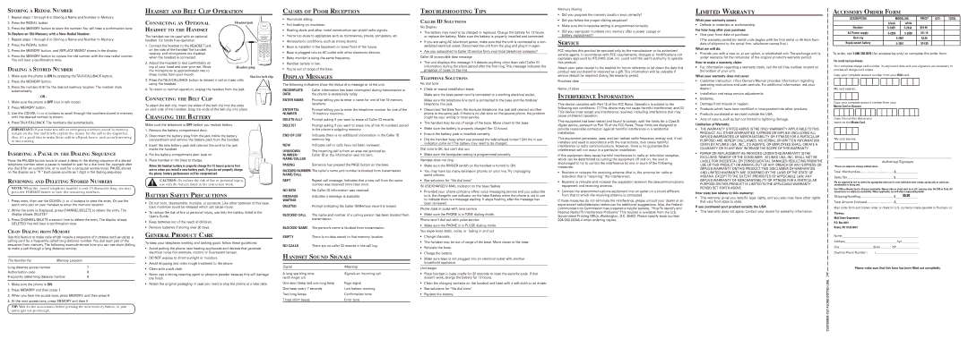
CONNECTING AN OPTIONAL | Headset jack | | |
HEADSET TO THE HANDSET | | | |
The handset can be used with an optional | | cid/vol | |
| TALK | |
headset for hands free operation. | | CALL BACK | |
| delete | | |
| redial | | format |
1. Connect the headset to the HEADSET jack | 1 | 2 ABC | 3 DEF |
4 GHI | 5 JKL | 6 MNO |
on the side of the handset The handset | cancel | 8 TUV | 9 WXYZ |
receiver and microphone are disabled | 7PQRS |
delete | mem | program |
| * TONE | 0OPER | # PAUSE |
when the headset is connected. | chan | | flash |
| | ringer | |
| | off on | |
2. Adjust the headset to rest comfortably on
top of your head and over your ear. MoveHeadset plug the microphone to approximately two to
three inches from your mouth.
Slot for belt clip
3.Press the TALK/CALLBACK button to answer a call or make calls using the headset.
4.To return to normal operation, unplug the headset from the jack.
CONNECTING THE BELT CLIP
To attach the belt clip, insert the sides of the belt clip into the slots on each side of the handset. Snap the ends of the belt clip into place.
CHANGING THE BATTERY
Make sure the telephone is OFF before you replace battery.
1.Remove the battery compartment door.
2.Disconnect the battery plug from the jack inside the battery compartment and remove the battery pack from the handset.
3.Insert the new battery pack and connect the cord to the jack inside the handset.
4.Put the battery compartment door back on.
5.Place handset in the base to charge.
Allow the handset battery to properly charge (for 12 hours) prior to first use or when you install a new battery pack. If you do not properly charge the phone, battery performance will be compromised.
CAUTION: To reduce the risk of fire or personal injury, use only the battery listed in the instruction book.
BATTERY SAFETY PRECAUTIONS
•Do not burn, disassemble, mutilate, or puncture. Like other batteries of this type, toxic materials could be released which can cause injury.
•To reduce the risk of fire or personal injury, use only the battery listed in the User’s Guide.
•Keep batteries out of the reach of children.
•Remove batteries if storing over 30 days.
GENERAL PRODUCT CARE
To keep your telephone working and looking good, follow these guidelines:
• | Avoid putting the phone near heating appliances and devices that generate |
| electrical noise (for example, motors or fluorescent lamps). |
• | DO NOT expose to direct sunlight or moisture. |
CAUSES OF POOR RECEPTION
•Aluminum siding.
•Foil backing on insulation.
•Heating ducts and other metal construction can shield radio signals.
•You’re too close to appliances such as microwaves, stoves, computers, etc.
•Atmospheric conditions, such as strong storms.
•Base is installed in the basement or lower floor of the house.
•Base is plugged into an AC outlet with other electronic devices.
•Baby monitor is using the same frequency.
•Handset battery is low.
•You’re out of range of the base.
DISPLAY MESSAGES
The following indicators show the status of a message or of the unit.
Caller information has been interrupted during transmission or the phone is excessively noisy.
Prompt telling you to enter a name for one of the 10 memory locations.
Prompt telling you to enter the telephone number for one of the 10 memory locations.
Prompt asking if you want to erase all Caller ID records.
Prompt asking if you want to erase one of the 10 numbers stored in the phone's outgoing memory.
Indicates there is no additional information in the Caller ID memory log.
Indicates call or calls have not been reviewed.
The incoming call is from an area not serviced by
Caller ID or the information was not sent.
Someone has pressed the PAGE button on the base.
BLOCKED NUMBER/ The caller’s name and number is blocked from transmission.
NAME/CALL
REPT | Repeat call message. Indicates that a new call from the same |
| number was received more than once. |
NO DATA | No Caller ID information was received. |
MESSAGE | Indicates a message is available. |
WAITING | |
DELETED | Prompt indicating the Caller ID/Memory record is erased. |
BLOCKED CALL | The name and number of a calling person has been blocked from |
| transmission. |
BLOCKED NAME | The person’s name is blocked from transmission. |
EMPTY | There is no data stored in that memory location. |
NO CALLS | There are no caller ID records in the call log. |
HANDSET SOUND SIGNALS
TROUBLESHOOTING TIPS
CALLER ID SOLUTIONS
No Display
•The battery may need to be charged or replaced. Charge the battery for 12 hours or replace the battery. Make sure the battery is properly installed and connected.
•If you are using AC (electrical) power, make sure that the unit is connected to a non- switched electrical outlet. Disconnect the unit from the plug and plug it in again.
•Are you subscribed to Caller ID service from your local telephone company? Caller ID incomplete data message
•The unit displays this message if it detects anything other than valid Caller ID information during the silent period after the first ring. This message indicates the presence of noise on the line.
TELEPHONE SOLUTIONS
No dial tone
•Check or repeat installation steps:
Make sure the base power cord is connected to a working electrical outlet.
Make sure the telephone line cord is connected to the base and the modular telephone line jack.
•Disconnect the base from the modular telephone line jack and connect another phone to the same jack. If there is no dial tone on the second phone, the problem might be your wiring or local service.
•The handset may be out of range of the base. Move closer to the base.
•Make sure the battery is properly charged (for 12 hours).
•Ensure the battery pack is installed correctly.
•Did the handset beep when you pressed the talk/callback button? Did the in use indicator come on? The battery may need to be charged.
Dial tone is OK, but can't dial out
• Make sure the tone/pulse setting is programmed correctly.
Handset does not ring
•Make sure the RINGER switch on the handset is turned to ON.
•You may have too many extension phones on your line. Try unplugging some phones.
•See solutions for “No dial tone.”
IN USE/CHARGE/V-MAIL Indicator on the base flashes
•Provided your phone company offers voice messaging service and you subscribe to it, the charge/in use indicator on the base flashes when the phone is not in use to indicate there is a message waiting. It stops flashing after the message has been reviewed.
Phone dials in pulse with tone service
•Make sure the PHONE is in TONE dialing mode. Phone won’t dial out with pulse service
•Make sure the PHONE is in PULSE dialing mode.
You experience static, noise, or fading in and out
• | Change channels. |
• The handset may be out of range of the base. Move closer to the base. |
• | Relocate the base. |
• | Charge the battery. |
• Make sure base is not plugged into an electrical outlet with another |
Memory Dialing
•Did you program the memory location keys correctly?
•Did you follow the proper dialing sequence?
•Make sure the tone/pulse setting is programmed correctly.
•Did you reprogram numbers into memory after a power outage or battery replacement?
SERVICE
FCC requires this product be serviced only by the manufacturer or its authorized service agents. In accordance with FCC requirements, changes or modifications not expressly approved by ATLINKS USA, Inc. could void the user’s authority to operate this product.
Attach your sales receipt to the booklet for future reference or jot down the date this product was purchased or received as a gift. This information will be valuable if service should be required during the warranty period.
Purchase date __________________________________________________________________
Name of store __________________________________________________________________
INTERFERENCE INFORMATION
This device complies with Part 15 of the FCC Rules. Operation is subject to the following two conditions: (1) This device may not cause harmful interference; and (2) This device must accept any interference received, including interference that may cause undesired operation.
This equipment has been tested and found to comply with the limits for a Class B digital device, pursuant to Part 15 of the FCC Rules. These limits are designed to provide reasonable protection against harmful interference in a residential installation.
This equipment generates, uses, and can radiate radio frequency energy and, if not installed and used in accordance with the instructions, may cause harmful interference to radio communications. However, there is no guarantee that interference will not occur in a particular installation.
If this equipment does cause harmful interference to radio or television reception, which can be determined by turning the equipment off and on, the user is encouraged to try to correct the interference by one or more of the following measures:
•Reorient or relocate the receiving antenna (that is, the antenna for radio or television that is “receiving” the interference).
•Reorient or relocate and increase the separation between the telecommunications equipment and receiving antenna.
•Connect the telecommunications equipment into an outlet on a circuit different from that to which the receiving antenna is connected.
If these measures do not eliminate the interference, please consult your dealer or an experienced radio/television technician for additional suggestions. Also, the Federal Communications Commission has prepared a helpful booklet, “How To Identify and Resolve Radio/TV Interference Problems.” This booklet is available from the U.S. Government Printing Office, Washington, D.C. 20402. Please specify stock number 004-000-00345-4 when ordering copies.
LIMITED WARRANTY
What your warranty covers:
•Defects in materials or workmanship.
For how long after your purchase:
•One year, from date of purchase.
(The warranty period for rental units begins with the first rental or 45 days from date of shipment to the rental firm, whichever comes first.)
What we will do:
•Provide you with a new or, at our option, a refurbished unit. The exchange unit is under warranty for the remainder of the original product’s warranty period.
How to make a warranty claim:
•For information regarding a warranty claim, call the toll free number located on the bottom of your unit.
What your warranty does not cover:
•Customer instruction. (Your Owner’s Manual provides information regarding operating instructions and user controls. For additional information, ask your dealer.)
•Installation and setup service adjustments.
•Batteries.
•Damage from misuse or neglect.
•Products which have been modified or incorporated into other products.
•Products purchased or serviced outside the USA.
•Acts of nature, such as but not limited to lightning damage.
Limitation of Warranty:
•THE WARRANTY STATED ABOVE IS THE ONLY WARRANTY APPLICABLE TO THIS PRODUCT. ALL OTHER WARRANTIES, EXPRESS OR IMPLIED (INCLUDING ALL IMPLIED WARRANTIES OF MERCHANTABILITY OR FITNESS FOR A PARTICULAR PURPOSE) ARE HEREBY DISCLAIMED. NO VERBAL OR WRITTEN INFORMATION GIVEN BY ATLINKS USA, INC., ITS AGENTS, OR EMPLOYEES SHALL CREATE A GUARANTY OR IN ANY WAY INCREASE THE SCOPE OF THIS WARRANTY.
•REPAIR OR REPLACEMENT AS PROVIDED UNDER THIS WARRANTY IS THE EXCLUSIVE REMEDY OF THE CONSUMER. ATLINKS USA, INC. SHALL NOT BE LIABLE FOR INCIDENTAL OR CONSEQUENTIAL DAMAGES RESULTING FROM THE USE OF THIS PRODUCT OR ARISING OUT OF ANY BREACH OF ANY EXPRESS OR IMPLIED WARRANTY ON THIS PRODUCT. THIS DISCLAIMER OF WARRANTIES AND LIMITED WARRANTY ARE GOVERNED BY THE LAWS OF THE STATE OF INDIANA. EXCEPT TO THE EXTENT PROHIBITED BY APPLICABLE LAW, ANY IMPLIED WARRANTY OF MERCHANTABILITY OR FITNESS FOR A PARTICULAR PURPOSE ON THIS PRODUCT IS LIMITED TO THE APPLICABLE WARRANTY PERIOD SET FORTH ABOVE.
How state law relates to this warranty:
•This warranty gives you specific legal rights, and you also may have other rights that vary from state to state.
If you purchased your product outside the USA:
•This warranty does not apply. Contact your dealer for warranty information.
ACCESSORY ORDER | FORM | | | | | |
| | DESCRIPTION | | | | | MODEL NO. | | PRICE* | QTY. | | TOTAL | |
| | | | | | | | | | black | | white | | | | | | |
| | | Headset | | | 5-2425 | | 5-2444 | | $19.95 | | | | |
| | AC Power supply | | | 5-2559 | | 5-2558 | | $11.15 | | | | |
| | | Belt clip | | | | | | 5-2567 | | $3.25 | | | | |
| | | | | | | | | | | | | |
| Replacement battery | | | | | | 5-2461 | | $14.95 | | | | |
To order, call 1-800-338-0376(for accessories only) or complete this order form. | | |
| For credit card purchases | | | | | | | | | | | | | |
| Your complete charge card number, its expiration date and your signature are necessary to | |
| process all charge card orders. | | | | | | | | | | | | | |
| Copy your complete account number from your VISA card. | | | | | |
| | | | | | | | | | | | | | | | | | | |
| | | | | | | | | | | | | | | | | | | |
| My card expires: | | | | | | | | | | | | | |
| Copy your complete account number from your | | | | | |
| Master Card or Discover. | | | | | | | | | | | | | |
| | | | | | | | | | | | | | | | | |
| Copy the number above your | | | | | | | | | | | | | |
| name on the Master Card. | | | | | | | | | | | | | |
| My card expires: | | | | | | | | | | | | | |
| | | | | | | | | | | | | | |
| | | | | | | | | | | | | | | | | | | |
____________________________________________________________________ | |
| | | | | | | | Authorized Signature | | | | | |
| *Prices are subject to change without notice. | | | | | | | | | | | |
| Total Merchandise | | $_______________ | | | | | |
| Sales Tax | | $_______________ | | | | | |
| We are required by law to collect the appropriate sales tax for each individual state, county, and locality to which the | |
| merchandise is being sent. | | | | | | | | | | | | | |
| Use VISA or Master Card or Discover preferably. Money order or check must be in U.S. currency only. No COD or Cash. All | |
| accessories are subject to availability. Where applicable, we will ship a superseding model. | | | | |
| Shipping/Handling | | $ | $5.00 | | | | | | |
| | _______________ | | | | | |
| Total Amount Enclosed | | $_______________ | | | | | |
| Mail order form and money order or check (in U.S. currency) made payable to Thomson to: | |
| Thomson | | | | | | | | | | | | | |
| Mail Order Department | | | | | | | | | | | | | |
| P.O. Box 8419 | | | | | | | | | | | | | |
| Ronks, PA 17573-8419 | | | | | | | | | | | | | |
| Name_______________________________________________________ | | | | | |
| Address_____________________________________ Apt.____________ | | | | | |
| City ________________________State________ ZIP_________________ | | | | | |
| Daytime Phone Number ( | )_______________________________ | | | | | |