GENERAL SAFETY INFORMATION

(Continued)

CAUTION: FOR GENERAL VENTILATING USE ONLY. DO NOT USE TO EXHAUST HAZARDOUS OR EXPLOSIVE MATERIALS AND VAPORS.

6.

When cutting or drilling into wall or ceiling, do not damage electrical


wiring and other hidden utilities.

7.

Ducted fans must always be vented to the outdoors.

8.

This unit must be grounded.

9.

To avoid motor bearing damage and noisy and/or unbalanced

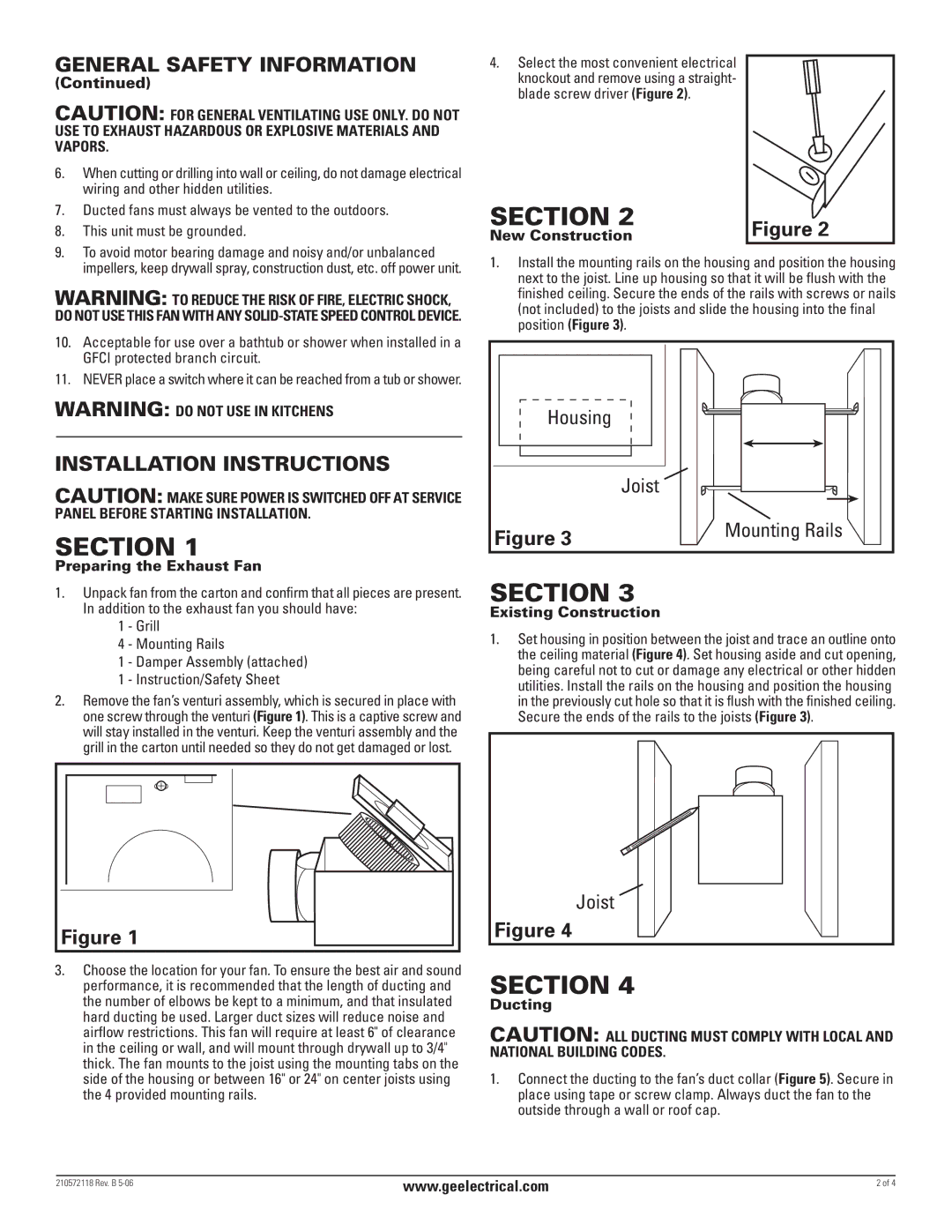
4.Select the most convenient electrical knockout and remove using a straight- blade screw driver (Figure 2).

SECTION 2

New Construction

Figure 2

impellers, keep drywall spray, construction dust, etc. off power unit.

WARNING: TO REDUCE THE RISK OF FIRE, ELECTRIC SHOCK, DO NOT USE THIS FAN WITH ANY SOLID-STATE SPEED CONTROL DEVICE.

10.Acceptable for use over a bathtub or shower when installed in a GFCI protected branch circuit.

11.NEVER place a switch where it can be reached from a tub or shower.

WARNING: DO NOT USE IN KITCHENS

INSTALLATION INSTRUCTIONS

CAUTION: MAKE SURE POWER IS SWITCHED OFF AT SERVICE PANEL BEFORE STARTING INSTALLATION.

SECTION 1

Preparing the Exhaust Fan

1.Unpack fan from the carton and confirm that all pieces are present. In addition to the exhaust fan you should have:

1- Grill

4- Mounting Rails

1- Damper Assembly (attached)

1- Instruction/Safety Sheet

2.Remove the fan’s venturi assembly, which is secured in place with one screw through the venturi (Figure 1). This is a captive screw and will stay installed in the venturi. Keep the venturi assembly and the grill in the carton until needed so they do not get damaged or lost.

Figure 1

3.Choose the location for your fan. To ensure the best air and sound performance, it is recommended that the length of ducting and the number of elbows be kept to a minimum, and that insulated hard ducting be used. Larger duct sizes will reduce noise and airflow restrictions. This fan will require at least 6" of clearance in the ceiling or wall, and will mount through drywall up to 3/4" thick. The fan mounts to the joist using the mounting tabs on the side of the housing or between 16" or 24" on center joists using the 4 provided mounting rails.

1.Install the mounting rails on the housing and position the housing next to the joist. Line up housing so that it will be flush with the finished ceiling. Secure the ends of the rails with screws or nails (not included) to the joists and slide the housing into the final position (Figure 3).

Housing


Joist

Figure 3

Mounting Rails


SECTION 3

Existing Construction

1.Set housing in position between the joist and trace an outline onto the ceiling material (Figure 4). Set housing aside and cut opening, being careful not to cut or damage any electrical or other hidden utilities. Install the rails on the housing and position the housing in the previously cut hole so that it is flush with the finished ceiling. Secure the ends of the rails to the joists (Figure 3).

Joist

Figure 4

SECTION 4

Ducting

CAUTION: ALL DUCTING MUST COMPLY WITH LOCAL AND NATIONAL BUILDING CODES.

1.Connect the ducting to the fan’s duct collar (Figure 5). Secure in place using tape or screw clamp. Always duct the fan to the outside through a wall or roof cap.

210572118 Rev. B 5-06

www.geelectrical.com

2 of 4


Page 2
Image 2
GE BF150A, BF120 manual General Safety Information, Installation Instructions

BF150A, BF120, BF150 specifications

The GE BF series of generators, specifically the BF150, BF120, and BF150A models, are known for their reliability and performance in various applications. These models are designed to provide efficient energy solutions for industrial, commercial, and residential use.

The GE BF150 is particularly recognized for its robust power output and efficiency. It features a powerful engine that delivers a dependable 150 kVA of power, making it suitable for heavy-duty applications. The generator is equipped with advanced cooling systems that ensure optimal performance even in harsh conditions. Its compact design allows for easy installation and transport, providing flexibility for businesses on the go.

The BF120 model stands out for its balance between power and size. With a rated output of 120 kVA, this generator is ideal for smaller operations that need reliable power without the bulk of larger systems. It includes an intuitive control panel that simplifies operation and monitoring, making it user-friendly. The BF120 is also known for its low noise levels and fuel efficiency, making it an excellent choice for urban environments or noise-sensitive areas.

The BF150A model builds upon the strengths of the BF150 with enhancements in technology and efficiency. It incorporates modern digital controls that provide real-time monitoring and management of the generator's performance. This model is designed with an emphasis on environmental sustainability, featuring reduced emissions and improved fuel consumption rates. The BF150A is equipped with advanced safety features, including automatic shutdown in case of low oil pressure or overheating, which enhances reliability.

All three models in the GE BF series share common characteristics such as durable construction and ease of maintenance, ensuring longevity and consistent performance. Each unit is designed with versatile mounting options, allowing users to customize their setup based on space and operational requirements. The generators also offer a variety of fuel options, including diesel and natural gas, providing flexibility to meet different environmental regulations and fuel availability.

In summary, the GE BF150, BF120, and BF150A generators are engineered to meet the diverse power needs of users while maximizing efficiency and minimizing environmental impact. With their robust features and advanced technology, these models are a solid investment for anyone seeking reliable and effective power solutions.