BFL125UQ

Ultra Quiet Bath Fan with Light/Night Light User’s Guide

Item Stock Number(s): BFL125UQ

READ AND SAVE THESE INSTRUCTIONS

Important Safety Instructions

CAUTION: The equipment covered by these instructions should be installed and serviced only by competent personnel utilizing proper safety practices and procedures. These instructions are written for such personnel and are not intended as a substitute for adequate training and experience in safe procedures for this type of equipment.

Warning: Disconnect the power at service panel before beginning this installation.

Caution: To reduce the risk of fire and to properly exhaust air, be sure to duct air outside. Do not vent exhaust air into spaces within walls or ceilings, or into attics, crawl spaces, or garages.

Acceptable for use over tub or shower when installed in a GFCI protected branch circuit.

Warning: To reduce the risk of fire or electric shock, do not use this fan with any solid- state speed control device.

Caution: For general ventilating use only. Do not use to exhaust hazardous or explosive materials and vapors.

Warning: Do not use in kitchens.

To ensure the best air and sound performance, it is recommended that the length of ducting and the number of elbows be kept to a minimum, and that insulated hard ducting be used. Larger duct sizes will reduce noise and airflow restriction.

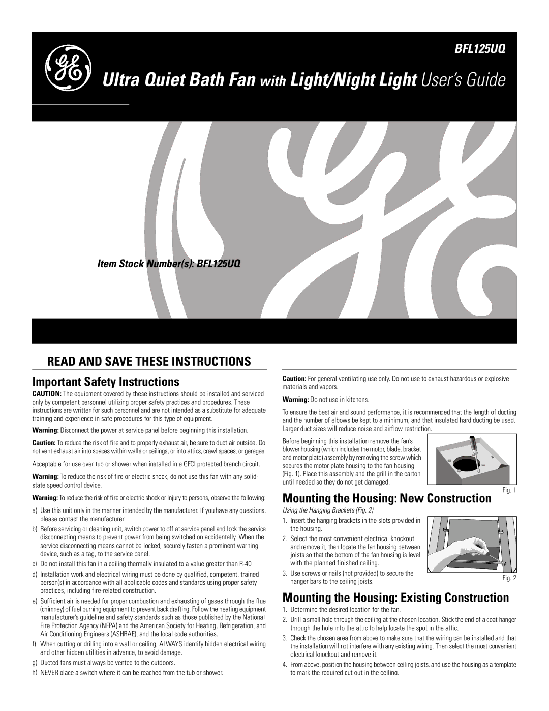
Before beginning this installation remove the fan’s

blower housing (which includes the motor, blade, bracket

and motor plate) assembly by removing the screw which secures the motor plate housing to the fan housing (Fig. 1). Place this assembly and the grill in the carton

until needed so they do not get damaged.

Fig. 1

Warning: To reduce the risk of fire or electric shock or injury to persons, observe the following:

a)

Use this unit only in the manner intended by the manufacturer. If you have any questions,


please contact the manufacturer.

b)

Before servicing or cleaning unit, switch power to off at service panel and lock the service


disconnecting means to prevent power from being switched on accidentally. When the


service disconnecting means cannot be locked, securely fasten a prominent warning


device, such as a tag, to the service panel.

c)

Do not install this fan in a ceiling thermally insulated to a value greater than R-40

d)

Installation work and electrical wiring must be done by qualified, competent, trained

Mounting the Housing: New Construction

Using the Hanging Brackets (Fig. 2)

1.Insert the hanging brackets in the slots provided in the housing.

2.Select the most convenient electrical knockout and remove it, then locate the fan housing between joists so that the bottom of the fan housing is level with the planned finished ceiling.

3.Use screws or nails (not provided) to secure the

person(s) in accordance with all applicable codes and standards using proper safety

practices, including fire-related construction.

hanger bars to the ceiling joists.

Fig. 2

e)

Sufficient air is needed for proper combustion and exhausting of gases through the flue


(chimney) of fuel burning equipment to prevent back drafting. Follow the heating equipment


manufacturer’s guideline and safety standards such as those published by the National


Fire Protection Agency (NFPA) and the American Society for Heating, Refrigeration, and


Air Conditioning Engineers (ASHRAE), and the local code authorities.

f)

When cutting or drilling into a wall or ceiling, ALWAYS identify hidden electrical wiring


and other hidden utilities in advance, to avoid damage.

g)

Ducted fans must always be vented to the outdoors.

h)

NEVER place a switch where it can be reached from the tub or shower.

Mounting the Housing: Existing Construction

1.Determine the desired location for the fan.

2.Drill a small hole through the ceiling at the chosen location. Stick the end of a coat hanger through the hole into the attic to help locate the spot in the attic.

3.Check the chosen area from above to make sure that the wiring can be installed and that the installation will not interfere with any existing wiring. Then select the most convenient electrical knockout and remove it.

4.From above, position the housing between ceiling joists, and use the housing as a template to mark the required cut out in the ceiling.

Page 1
Image 1
GE BFL125UQ warranty Important Safety Instructions, Mounting the Housing New Construction

BFL125UQ specifications

The GE BFL125UQ is a robust and versatile circuit breaker designed for residential and commercial applications, ensuring both safety and reliability in electrical systems. This model has gained recognition for its advanced features and technologies that meet the demands of modern electrical installations.

One of the standout characteristics of the GE BFL125UQ is its 125-amp rating, which makes it suitable for a variety of load requirements. This circuit breaker is designed to protect lighting, receptacles, and other circuits from overloads and short circuits. The BFL125UQ’s thermal-magnetic design provides dual protection, responding to both slow surges and fast short-circuit events.

The GE BFL125UQ incorporates an easy-to-read trip indicator, allowing users to quickly assess the operational status of the circuit breaker. This feature is particularly useful during troubleshooting or maintenance, as it provides immediate feedback whether the breaker has tripped due to an overload or another fault.

Another prominent technology featured in the BFL125UQ is its compact design, which optimizes space within electrical panels. This is crucial in environments where space is at a premium, allowing for more circuits without sacrificing performance or safety. Its compatibility with a range of panel boards further enhances its applicability across different installations.

The BFL125UQ also emphasizes safety through its dielectric strength, ensuring reliable performance even under challenging conditions. This circuit breaker is UL listed, meeting stringent safety standards and providing users with peace of mind regarding its reliability.

In addition, the GE BFL125UQ incorporates user-friendly installation features. Its mounting mechanism simplifies installation for electricians, minimizing labor time and costs. The breaker’s robust construction ensures long-term durability, making it a preferred choice for both new constructions and upgrades in existing electrical systems.

Overall, the GE BFL125UQ circuit breaker stands out for its advanced protective features, compact design, and user-friendly installation. Its ability to safeguard electrical systems effectively while ensuring ease of use makes it a popular choice among professionals in the industry.