F485 COMMUNICATIONS CONVERTER | Page 4 of 8 |
CONNECTIONS
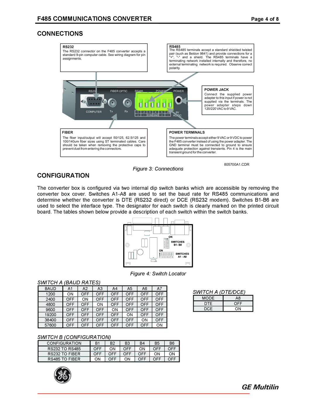
RS232
The RS232 connector on the F485 converter accepts a standard
RS485
The RS485 terminals accept a standard shielded twisted pair (such as Beldon 9841) and provide connections for a "+",
RS232 | FIBER OPTIC | RS485 |
|
| POWER |
| POWER | ||
COMPUTER | Tx | Rx | 1 | 2 | 3 | 4 | 5 | 6 | 9V |
|
| ||||||||
|
|
| + | - | COM GND | + | - | AC/DC | |
|
|
|
|
| |||||
POWER JACK
Connect the supplied power adapter to this input if power is not supplied via the terminals. The power adapter steps down 120/220 VAC to 9 VAC.
FIBER
The fiber input/output will accept 50/125, 62.5/125 and 100/140um fiber sizes using ST terminated cables. Care should be taken when removing the protective caps to prevent dust from entering the connectors.
POWER TERMINALS
The power terminals accept either 9 VAC or 9 VDC to power the F485 converter instead of using the power adapter. The GND terminal must be connected to ground to ensure adaquate protection against transients. Pin 4 is the main transient ground for the converter.
805700A1.CDR
Figure 3: Connections
CONFIGURATION
The converter box is configured via two internal dip switch banks which are accessible by removing the converter box cover. Switches
Figure 4: Switch Locator
SWITCH A (BAUD RATES)
|
| BAUD |
|
| A1 |
|
| A2 |
|
| A3 |
|
| A4 |
|
| A5 |
|
| A6 |
|
| A7 |
|
|
| SWITCH A (DTE/DCE) |
| ||
|
| 1200 |
|
| ON |
| OFF |
|
| OFF |
|
| OFF |
|
| OFF |
|
| OFF |
|
| OFF |
|
|
|
| ||||
|
| 2400 |
|
| OFF |
|
| ON |
|
| OFF |
|
| OFF |
|
| OFF |
|
| OFF |
|
| OFF |
|
|
| MODE |
| A8 |
|
|
| 4800 |
|
| OFF |
|
| OFF |
|
| ON |
|
| OFF |
|
| OFF |
|
| OFF |
|
| OFF |
|
|
| DTE |
| OFF |
|
|
| 9600 |
|
| OFF |
|
| OFF |
|
| OFF |
|
| ON |
|
| OFF |
|
| OFF |
|
| OFF |
|
|
| DCE |
| ON |
|
|
| 19200 |
|
| OFF |
|
| OFF |
|
| OFF |
|
| OFF |
|
| ON |
|
| OFF |
|
| OFF |
|
|
|
|
|
|
|
|
| 38400 |
|
| OFF |
|
| OFF |
|
| OFF |
|
| OFF |
|
| OFF |
|
| ON |
|
| OFF |
|
|
|
|
|
|
|
|
| 57600 |
|
| OFF |
|
| OFF |
|
| OFF |
|
| OFF |
|
| OFF |
|
| OFF |
|
| ON |
|
|
|
|
|
|
|
SWITCH B (CONFIGURATION) |
|
|
|
|
|
|
|
|
|
|
|
|
|
|
|
| ||||||||||||||
|
| CONFIGURATION |
| B1 |
| B2 |
| B3 |
| B4 |
| B5 |
| B6 |
|
|
|
|
| |||||||||||
|
| RS232 TO RS485 |
|
| OFF |
| ON |
| OFF |
| ON |
| OFF |
| OFF |
|
|
|
|
| ||||||||||
|
| RS232 TO FIBER |
|
| OFF |
| OFF |
| OFF |
| OFF |
| ON |
| ON |
|
|
|
|
| ||||||||||
|
| RS485 TO FIBER |
|
| ON |
| OFF |
| ON |
| OFF |
| OFF |
| OFF |
|
|
|
|
| ||||||||||
g