SINGLE STAGE COLD ROOM PANEL
*(9&3/
Applicable to model numbers: 2051/52/53/54/55/56
DESCRIPTION
The VCPL series is especially designed for use in the commercial refrigeration and is available in various different models. The VCPL is also available with communication properties.
In addition to extremely accurate temperature control the VCPL offers the user diagnostics, marketing information and current statistics scroll i.e. average temperature, lowest temperature, highest temperature, number of door openings, compressor cycles and compressor running hours.
As standard all models in the VCPL series are fitted with 6 relays switching : compressor, heating element or solenoid valve, external alarm, evaporator fan, on/off switch and light(s). All relays in this unit have a switching capacity of 16 Amp. @ 240 Volt.
WARNING
This manual is part of the product and should be kept near the instrument for quick reference.
The instrument should not be used for purposes other than described and/or specified by the manufacturer. These controls can only be used with GE double insulated sensors.
SAFETY PRECAUTIONS
Ensure that the supply voltage is correct before connecting the instrument. (240 Volt )
Ensure that the instrument is not exposed to water or any other liquid.
Ensure that the current that is switched does not exceed the maximum switching capacity of the instrument. If the current to be switched is greater than the instrument limits, a separate relay should be installed.
Ensure that all wires are properly connected in the appropriate terminal, a loose wire could cause sparking and damage the instrument and may be dangerous.
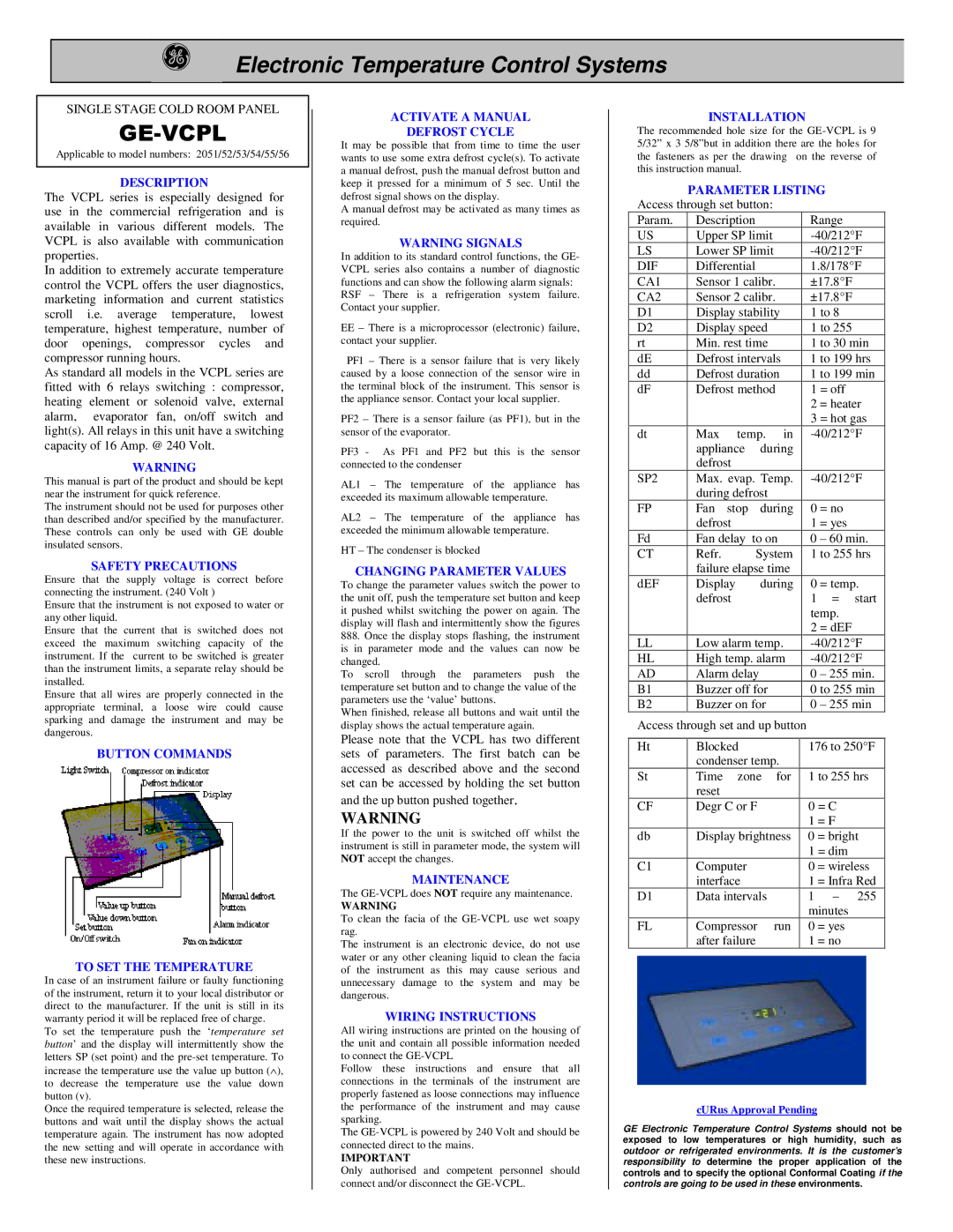
BUTTON COMMANDS
TO SET THE TEMPERATURE
In case of an instrument failure or faulty functioning of the instrument, return it to your local distributor or direct to the manufacturer. If the unit is still in its warranty period it will be replaced free of charge.
To set the temperature push the ‘temperature set button’ and the display will intermittently show the letters SP (set point) and the pre-set temperature. To increase the temperature use the value up button (∧ ), to decrease the temperature use the value down button (v).
Once the required temperature is selected, release the buttons and wait until the display shows the actual temperature again. The instrument has now adopted the new setting and will operate in accordance with these new instructions.
ACTIVATE A MANUAL
DEFROST CYCLE
It may be possible that from time to time the user wants to use some extra defrost cycle(s). To activate a manual defrost, push the manual defrost button and keep it pressed for a minimum of 5 sec. Until the defrost signal shows on the display.
A manual defrost may be activated as many times as required.
WARNING SIGNALS
In addition to its standard control functions, the GE- VCPL series also contains a number of diagnostic functions and can show the following alarm signals:
RSF – There is a refrigeration system failure. Contact your supplier.
EE– There is a microprocessor (electronic) failure, contact your supplier.
PF1 – There is a sensor failure that is very likely caused by a loose connection of the sensor wire in the terminal block of the instrument. This sensor is the appliance sensor. Contact your local supplier.
PF2 – There is a sensor failure (as PF1), but in the sensor of the evaporator.
PF3 - As PF1 and PF2 but this is the sensor connected to the condenser
AL1 – The temperature of the appliance has exceeded its maximum allowable temperature.
AL2 – The temperature of the appliance has exceeded the minimum allowable temperature.
HT – The condenser is blocked
CHANGING PARAMETER VALUES
To change the parameter values switch the power to the unit off, push the temperature set button and keep it pushed whilst switching the power on again. The display will flash and intermittently show the figures
888.Once the display stops flashing, the instrument is in parameter mode and the values can now be changed.
To scroll through the parameters push the temperature set button and to change the value of the parameters use the ‘value’ buttons.
When finished, release all buttons and wait until the display shows the actual temperature again.
Please note that the VCPL has two different sets of parameters. The first batch can be accessed as described above and the second set can be accessed by holding the set button and the up button pushed together.
WARNING
If the power to the unit is switched off whilst the instrument is still in parameter mode, the system will NOT accept the changes.
MAINTENANCE
The GE-VCPL does NOT require any maintenance.
WARNING
To clean the facia of the GE-VCPL use wet soapy rag.
The instrument is an electronic device, do not use water or any other cleaning liquid to clean the facia of the instrument as this may cause serious and unnecessary damage to the system and may be dangerous.
WIRING INSTRUCTIONS
All wiring instructions are printed on the housing of the unit and contain all possible information needed to connect the GE-VCPL
Follow these instructions and ensure that all connections in the terminals of the instrument are properly fastened as loose connections may influence the performance of the instrument and may cause sparking.
The GE-VCPL is powered by 240 Volt and should be connected direct to the mains.
IMPORTANT
Only authorised and competent personnel should connect and/or disconnect the GE-VCPL.