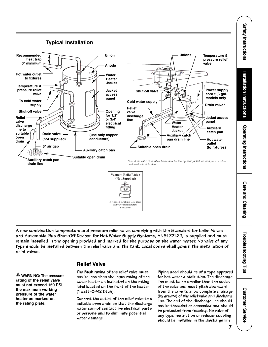
Typical Installation

Recommended


Union


Unions

Temperature &

heat trap


pressure relief

6minimum


Anode


valve


Hot water outlet


Water


to fixtures


Heater


Temperature &


Jacket


Power supply

pressure relief


Jacket

Shut-off valve


valve


access


cord 21/2 gal.

To cold water


panel

Cold water supply


models only


Drain valve*

supply


Relief


Shut-off valve


Opening


valve


Relief


for 1/2

discharge


Jacket access


or 3/4

line


valve


Water

panel


electrical


discharge


fitting


Heater

Auxiliary

line to


Jacket

catch pan

suitable

Drain valve


(use only copper

6

Auxiliary catch


open


(not supplied)

conductors)


pan drain line

Hot water

drain


outlet


6air gap


Suitable open drain


Auxiliary catch pan

(to fixtures)


Auxiliary catch pan

Suitable open drain


*The drain valve is located below and to the right of jacket access panel and is

drain line


not visible in this view.


Vacuum Relief Valve


(Not Supplied)


If required, install per local codes

and valve manufacturer’s

instructions.

A new combination temperature and pressure relief valve, complying with the Standard for Relief Valves and Automatic Gas Shut-Off Devices for Hot Water Supply Systems, ANSI Z21.22, is supplied and must remain installed in the opening provided and marked for the purpose on the water heater. No valve of any type should be installed between the relief valve and the tank. Local codes shall govern the installation of relief valves.

Safety Instructions Installation Instructions Operating Instructions Care and Cleaning Troubleshooting

WARNING: The pressure rating of the relief valve must not exceed 150 PSI, the maximum working pressure of the water heater as marked on the rating plate.

Relief Valve

The Btuh rating of the relief valve must not be less than the input rating of the water heater as indicated on the rating label located on the front of the heater (1 watt=3.412 Btuh).

Connect the outlet of the relief valve to a suitable open drain so that the discharge water cannot contact live electrical parts or persons and to eliminate potential water damage.

Piping used should be of a type approved for hot water distribution. The discharge line must be no smaller than the outlet of the valve and must pitch downward from the valve to allow complete drainage (by gravity) of the relief valve and discharge line. The end of the discharge line should not be threaded or concealed and should be protected from freezing. No valve of any type, restriction or reducer coupling should be installed in the discharge line.

Tips Customer Service

7

Page 7
Image 7
GE AP12169-5, GE Series important safety instructions Typical Installation, Relief Valve, Tips Customer Service

AP12169-5, GE Series specifications

The GE Series AP12169-5 represents a robust and versatile line of products designed by General Electric to cater to the diverse needs of modern industries. These units are characterized by their high efficiency, advanced technology, and user-friendly design, making them ideal for various applications, including industrial automation, HVAC systems, and power generation.

One of the standout features of the GE Series AP12169-5 is its energy efficiency. The product incorporates state-of-the-art energy-saving technologies that significantly reduce power consumption while optimizing performance. This aspect not only contributes to lower operational costs but also supports sustainability initiatives by minimizing the carbon footprint.

In addition to energy efficiency, the AP12169-5 series is equipped with advanced monitoring and control capabilities. These features allow for real-time performance analysis, thereby enabling operators to make informed decisions and implement timely adjustments. The built-in diagnostic tools assist in predictive maintenance, reducing downtime and enhancing the longevity of the equipment.

The GE Series AP12169-5 emphasizes ease of integration within existing systems. It supports various communication protocols, ensuring compatibility with a wide range of devices and frameworks. This flexibility facilitates seamless upgrades and expansions, making it an attractive option for businesses looking to enhance their operational efficiency without overhauling their entire infrastructure.

Another notable characteristic of the GE Series AP12169-5 is its durability. Built with high-quality materials and utilizing advanced manufacturing techniques, these units are designed to withstand harsh environments and demanding conditions. This reliability ensures continuous operation, which is crucial in industries where downtime can result in significant losses.

The user-friendly interface of the AP12169-5 also deserves mention. Its intuitive controls and comprehensive display simplify the operation and monitoring processes, making it accessible for personnel with varying levels of technical expertise. This feature translates to less training time and quicker adaptation to the system.

In summary, the GE Series AP12169-5 exemplifies a harmonious blend of efficiency, advanced technology, and robust durability. With its focus on energy savings, ease of integration, real-time monitoring, and user-friendly design, this product series is well-positioned to meet the evolving demands of industries worldwide. General Electric continues to demonstrate its commitment to innovation and excellence through the development of solutions that drive productivity and sustainability in the modern industrial landscape.