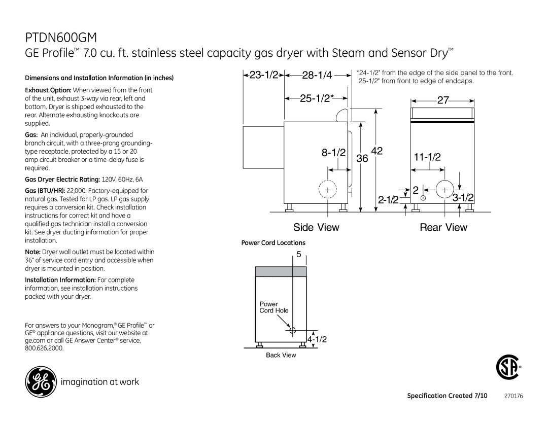
PTDN600GM, PTDN600EM specifications
The GE PTDN600GM and PTDN600EM are advanced transformer units designed to meet the demanding needs of modern electrical systems. These models are part of GE's commitment to providing reliable and efficient power solutions for various applications, including industrial, commercial, and utility-scale installations.One of the prominent features of the PTDN600GM and PTDN600EM models is their robust design, which ensures durability and a long operational life. Constructed with high-quality materials, these transformers are built to withstand harsh environmental conditions, providing peace of mind for operators in challenging locations. Their rugged enclosures are designed to protect internal components from moisture, dirt, and even extreme temperatures.
Both models incorporate advanced insulation technologies that improve performance while minimizing energy losses. The insulation systems used are designed to enhance the thermal performance and longevity of the transformers, contributing to their high-efficiency rating. This not only improves operational reliability but also offers potential savings in energy costs, a crucial factor for businesses seeking to enhance operational efficiency.
Another significant characteristic of the PTDN600GM and PTDN600EM is their modular design, which allows for easy transportation and installation. This modularity also enables simplified maintenance and quicker upgrades, offering significant advantages for projects requiring flexibility and scalability. The transformers can be integrated easily into existing electrical infrastructures, allowing for rapid deployment in various settings.
These transformer models are also equipped with cutting-edge monitoring technologies. The integration of smart sensors and digital monitoring solutions allows operators to track performance in real-time, providing insights on load conditions and potential maintenance needs. This proactive monitoring capability ultimately leads to reduced downtime, increased operational efficiency, and enhanced asset management.
Additionally, the GE PTDN600GM and PTDN600EM models are engineered with sustainability in mind. They utilize eco-friendly design practices and materials that help in reducing the carbon footprint, adhering to global standards for environmental responsibility.
In conclusion, the GE PTDN600GM and PTDN600EM transformers exemplify the latest advancements in transformer technology, combining reliability, efficiency, and smart monitoring features. With their robust construction, innovative insulation systems, modular design, and environmental focus, these transformers are well-suited for a diverse range of applications, making them ideal choices for meeting contemporary energy demands.

