INSTALLATION (CONT.): | |
Optional Alarm |
|
Terminal |
|
NO COM NC | |
| |
| LISTED (48E6) |
| UL 1449, 2ND EDITION |
| FOR INDOOR USE ONLY |
| NOTE: If lamp is out, replace unit |
| DUAL PHASE TVSS |
| 120 VAC 50/60HZ |
| SUPPRESSION VOLTAGES |
| 330 |
| 600 |
| TVSS |
| PART# ACT452120210N |
| DATE CODE: WO# |
30 A. / 22kAIC |
|
Max. |
|
| Black |
White
Green
TR451 Wiring Diagram
Optional Alarm |
|
Terminal |
|
NO COM NC | |
| |
| LISTED (48E6) |
| UL 1449, 2ND EDITION |
| FOR INDOOR USE ONLY |
| NOTE: If lamp is out, replace unit |
| DUAL PHASE TVSS |
| 120 VAC 50/60HZ |
| SUPPRESSION VOLTAGES |
| 330 |
| 600 |
| TVSS |
| PART# ACT452120210N |
| DATE CODE: WO# |
30 A. / 22kAIC Max.
Black
White |
Black |
Green |
TR452 Wiring Diagram
3.The TVSS can be installed in any orientation, however special consideration should be given to allow periodic visual inspection of the status indicator lamps.
CONNECTION
1.TR5451 and TR5452 Model TVSS units come equipped with 10 AWG connection wires to allow termination to the electrical system. It is important that the TVSS be installed in a location that is as close to the termination point as possible. Connection wires should be trimmed to prevent excessive lead length. Do not coil, loop or make sharp bends with the connection wires. Every inch of wire that can be trimmed away will aid the TVSS in it’s ability to provide the best possible protection level for your system.
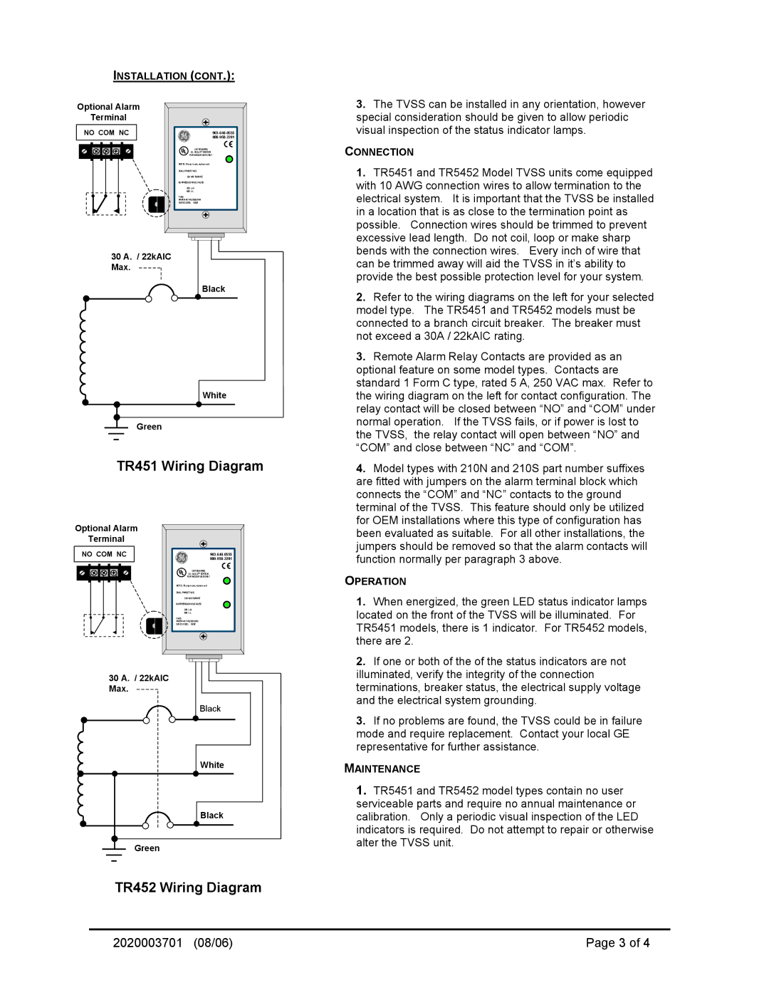
2.Refer to the wiring diagrams on the left for your selected model type. The TR5451 and TR5452 models must be connected to a branch circuit breaker. The breaker must not exceed a 30A / 22kAIC rating.
3.Remote Alarm Relay Contacts are provided as an optional feature on some model types. Contacts are standard 1 Form C type, rated 5 A, 250 VAC max. Refer to the wiring diagram on the left for contact configuration. The relay contact will be closed between “NO” and “COM” under normal operation. If the TVSS fails, or if power is lost to the TVSS, the relay contact will open between “NO” and “COM” and close between “NC” and “COM”.
4.Model types with 210N and 210S part number suffixes are fitted with jumpers on the alarm terminal block which connects the “COM” and “NC” contacts to the ground terminal of the TVSS. This feature should only be utilized for OEM installations where this type of configuration has been evaluated as suitable. For all other installations, the jumpers should be removed so that the alarm contacts will function normally per paragraph 3 above.
OPERATION
1.When energized, the green LED status indicator lamps located on the front of the TVSS will be illuminated. For TR5451 models, there is 1 indicator. For TR5452 models, there are 2.
2.If one or both of the of the status indicators are not illuminated, verify the integrity of the connection terminations, breaker status, the electrical supply voltage and the electrical system grounding.
3.If no problems are found, the TVSS could be in failure mode and require replacement. Contact your local GE representative for further assistance.
MAINTENANCE
1.TR5451 and TR5452 model types contain no user serviceable parts and require no annual maintenance or calibration. Only a periodic visual inspection of the LED indicators is required. Do not attempt to repair or otherwise alter the TVSS unit.
2020003701 (08/06) | Page 3 of 4 |