Advanced Operation
DIP Switch Configuration
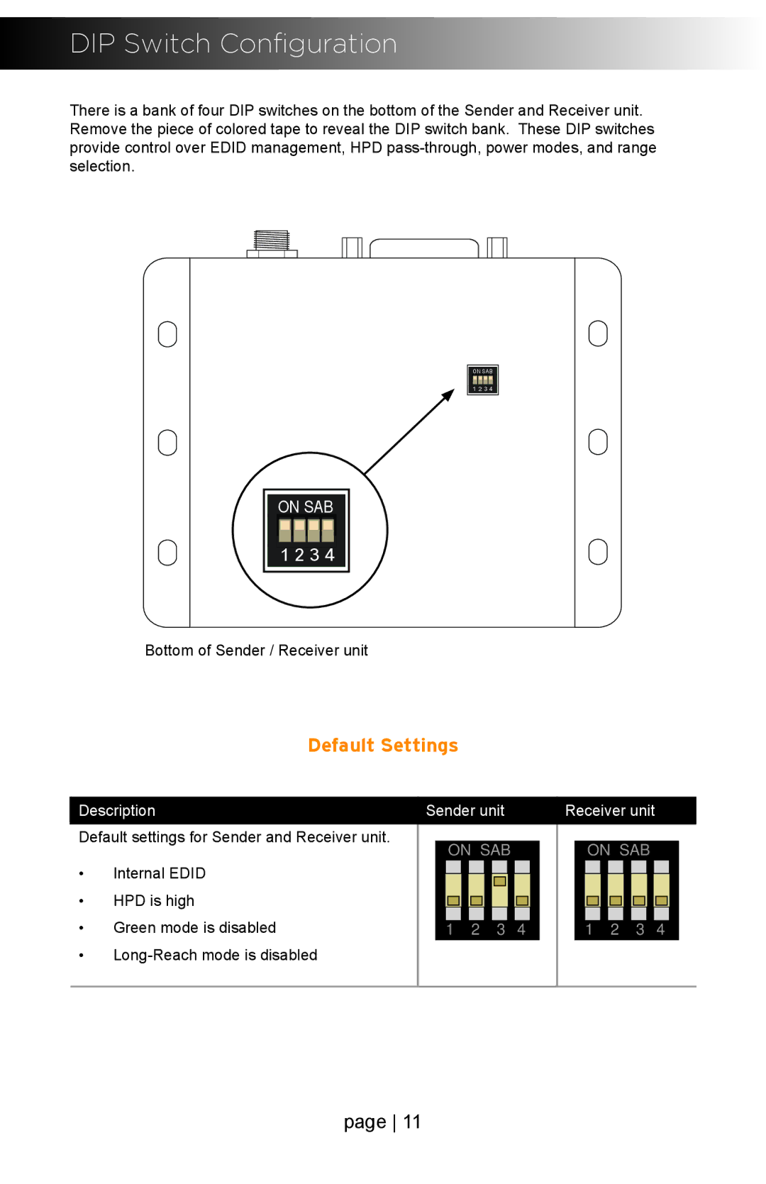
There is a bank of four DIP switches on the bottom of the Sender and Receiver unit. Remove the piece of colored tape to reveal the DIP switch bank. These DIP switches provide control over EDID management, HPD
ON SAB |
1 2 3 4 |
ON SAB
1 2 3 4 |
Bottom of Sender / Receiver unit
Default Settings
Description | Sender unit | Receiver unit | |||||||||||||||||||||
Default settings for Sender and Receiver unit. |
|
|
|
|
|
|
|
|
|
|
|
|
|
|
|
|
|
|
|
|
|
| |
|
| ON | SAB |
|
|
| ON | SAB |
| ||||||||||||||
• | Internal EDID |
|
|
|
|
|
| ||||||||||||||||
|
|
|
|
|
|
|
|
|
|
|
|
|
|
|
|
|
|
|
|
|
| ||
• | HPD is high |
|
|
|
|
|
|
|
|
|
|
|
|
|
|
|
|
|
|
|
|
|
|
|
|
|
|
|
|
|
|
|
|
|
|
|
|
|
|
|
|
|
|
|
| ||
• | Green mode is disabled |
| 1 2 | 3 4 |
|
| 1 2 | 3 4 |
| ||||||||||||||
•
page 11