EXT-HDMI1.3-841 specifications
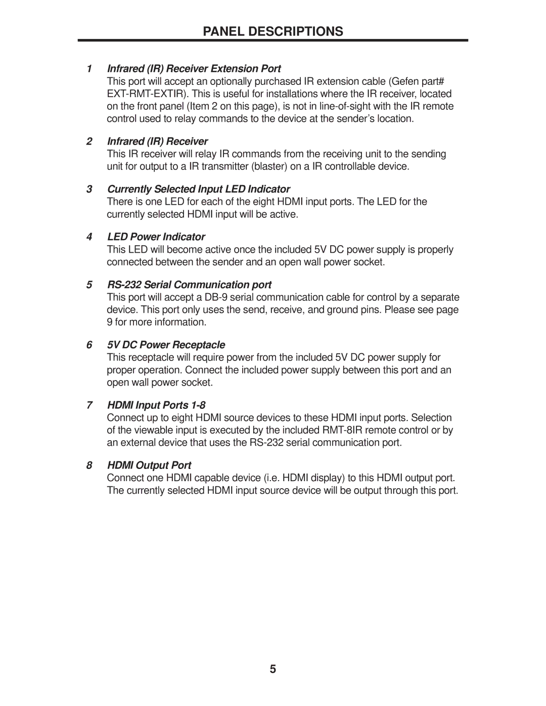
The Gefen EXT-HDMI1.3-841 is a high-performance HDMI splitter designed to cater to the modern demands of audio-visual enthusiasts. This device allows seamless distribution of a single HDMI source to multiple displays without compromising signal quality. It is an essential tool for settings such as home theaters, conference rooms, and event spaces where multiple viewing options are necessary.One of the standout features of the EXT-HDMI1.3-841 is its capability to transmit high-definition 1080p video and multi-channel audio across HDCP-compliant devices. This capability ensures that users can enjoy their favorite movies, television shows, and presentations with crystal-clear visuals and immersive sound. The splitter supports HDMI 1.3 specifications, making it compatible with a wide range of devices, including Blu-ray players, gaming consoles, and desktops.
With the ability to connect up to eight HDMI outputs simultaneously, the EXT-HDMI1.3-841 provides flexibility and convenience for various installations. This characteristic is particularly beneficial in commercial environments where multiple monitors may be required to display the same video feed. Moreover, it supports all HDMI features, including Deep Color, 3D support, and an audio return channel, enhancing overall connectivity options.
The device is designed for plug-and-play operation, which means that users can set it up quickly without needing extensive technical knowledge. Its robust design ensures durability and longevity, making it a reliable component in any AV setup. Furthermore, the EXT-HDMI1.3-841 includes LED indicators for each output, enabling users to effortlessly monitor device functionality and identify any potential issues swiftly.
The Gefen EXT-HDMI1.3-841 also includes advanced technologies such as EDID management, which simplifies compatibility between devices by communicating their preferences and capabilities effectively. This feature allows the splitter to optimize the signal sent to each connected display, ensuring the best possible visual experience.
In summary, the Gefen EXT-HDMI1.3-841 is a versatile HDMI splitter that meets the needs of both residential and commercial users. With its capacity to support multiple displays, exceptional video and audio quality, and user-friendly design, it stands out as a significant asset for any audio-visual setup. Whether for entertainment or professional presentations, this device delivers reliable performance and outstanding functionality.