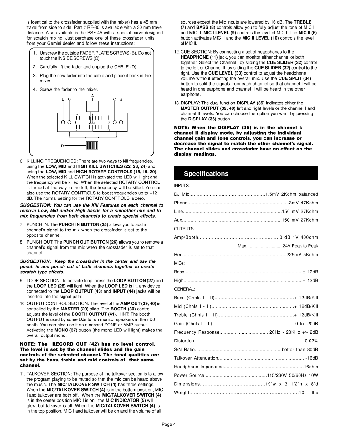
is identical to the crossfader supplied with the mixer) has a 45 mm travel from side to side. Part # RF-30 is available with a 30 mm travel distance. Also available is the PSF-45 with a special curve designed for scratch mixing. Just purchase one of these crossfader units from your Gemini dealer and follow these instructions:

1.Unscrew the outside FADER PLATE SCREWS (B). Do not touch the INSIDE SCREWS (C).

2.Carefully lift the fader and unplug the CABLE (D).

3.Plug the new fader into the cable and place it back in the mixer.

4.Screw the fader to the mixer.

6.KILLING FREQUENCIES: There are two ways to kill frequencies, using the LOW, MID and HIGH KILL SWITCHES (22, 23, 24) and using the LOW, MID and HIGH ROTARY CONTROLS (18, 19, 20). When the selected KILL SWITCH is activated the LED will light and the frequency will be killed. When the selected ROTARY CONTROL is turned all the way to the left, the frequency will be killed. You can also use the ROTARY CONTROLS to boost frequencies up to +12 dB. The normal setting for the ROTARY CONTROLS is zero.

SUGGESTION: You can use the Kill Features on each channel to remove Low, Mid and/or High bands for a smoother mix and to mix frequencies from both channels to create special effects.

7.PUNCH IN: The PUNCH IN BUTTON (25) allows you to add a channel’s signal to the mix when the crossfader is set to the opposite channel.

8.PUNCH OUT: The PUNCH OUT BUTTON (26) allows you to remove a channel’s signal from the mix when the crossfader is set to that channel.

SUGGESTION: Keep the crossfader in the center and use the punch in and punch out of both channels together to create scratch type effects.

9.LOOP SECTION: To activate loop, press the LOOP BUTTON (27) and the LOOP LED (28) will light. When the LOOP LED is lit, any device connected to the LOOP OUTPUT (43) and INPUT (44) jacks will be inserted into the signal path.

10.OUTPUT CONTROL SECTION: The level of the AMP OUT (39, 40) is controlled by the MASTER (29) slide. The BOOTH (30) control adjusts the level of the BOOTH OUTPUT (41). HINT: The booth OUTPUT is used by some DJs to run monitor speakers in their DJ booth. You can also use it as a second ZONE or AMP output. Activating the MONO (37) button (the mono LED will light) makes the overall output mono.

NOTE: The RECORD OUT (42) has no level control. The level is set by the channel slides and the gain controls of the selected channel. The tonal qualities are set by the bass, treble and mid controls of that same channel.

11.TALKOVER SECTION: The purpose of the talkover section is to allow the program playing to be muted so that the mic can be heard above the music. The MIC/TALKOVER SWITCH (4) has three settings.

When the MIC/TALKOVER SWITCH (4) is in the bottom position, MIC I and talkover are both off. When the MIC/TALKOVER SWITCH (4) is in the center position MIC I is on, the MIC INDICATOR (5) will glow, but talkover is off. When the MIC/TALKOVER SWITCH (4) is in the top position, MIC I and talkover will be on and the volume of all

sources except the Mic inputs are lowered by 16 dB. The TREBLE

(7) and BASS (8) controls allow you to fully adjust the tone of MIC I and MIC II. MIC I LEVEL (9) controls the level of MIC I. The MIC II (6) button activates MIC II and the MIC II LEVEL (10) controls the level of MIC II.

12.CUE SECTION: By connecting a set of headphones to the HEADPHONE (11) jack, you can monitor either channel or both together. Select the Channel I by sliding the CUE SLIDER (32) control to the left or Channel II by sliding the CUE SLIDER (32) control to the right. Use the CUE LEVEL (33) control to adjust the headphone volume without effecting the overall mix. Use the CUE SPLIT (34) button to split the signals from each channel so that channel I will be heard in one earphone and channel II will be heard in the other earphone.

13.DISPLAY: The dual function DISPLAY (35) indicates either the MASTER OUTPUT (39, 40) left and right levels or the channel I and channel II levels. You can choose the option you want by pressing the DISPLAY (36) button.

NOTE: When the DISPLAY (35) is in the channel I/ channel II display mode, by adjusting the individual channel gain and tone controls, you can increase or decrease the signal to match the other channel’s signal. The channel slides and crossfader have no effect on the display readings.

Specifications

INPUTS:


DJ Mic

1.5mV 2Kohm balanced

Phono

3mV 47Kohm

Line

150 mV 27Kohm

Aux

150 mV 27Kohm

OUTPUTS:


Amp/Booth

0 dB 1V 400ohm

Max

24V Peak to Peak

Rec

225mV 5Kohm

MICs:


Bass

± 12dB

High

± 12dB

GENERAL:


Bass (Chnls I - II)

+ 12dB/Kill

Mid (Chnls I - II)

+ 12dB/Kill

Treble (Chnls I - II)

+ 12dB/Kill

Gain (Chnls I - II)

0 to -20dB

Frequency Response

20Hz - 20KHz +/- 2dB

Distortion

0.02%

S/N Ratio

better than 80dB

Talkover Attenuation

-16dB

Headphone Impedance

16ohm

Power Source

115/230V 50/60Hz 10W

Dimensions

19”w x 3 1/2”h

x 8”d

Weight

10

lbs

Page 4

Page 5
Image 5
Gemini KL-19 manual Specifications, General

KL-19 specifications

The Gemini KL-19 is a cutting-edge spacecraft that exemplifies the advancements in space exploration technology. Designed for versatility and durability, it serves a range of purposes from scientific research to potential crewed missions beyond low Earth orbit.

One of the main features of the Gemini KL-19 is its advanced propulsion system. Utilizing hybrid engines that combine traditional chemical propulsion with innovative ion thrusters, the spacecraft is able to achieve greater efficiency and longer operational durations. This allows for both rapid maneuvers in low Earth orbit and prolonged missions in deeper space. The hybrid system not only enhances the spacecraft's range but also contributes to a reduced environmental footprint.

The Gemini KL-19 boasts a modular design, which is a crucial element in its functionality. The spacecraft can be equipped with various modules tailored to specific missions. This includes science laboratories for research, accommodation modules for astronauts on extended missions, and cargo storage for supplies. The modular system facilitates quick reconfiguration based on mission requirements, effectively making it a multifaceted tool for space agencies.

Another standout characteristic of the Gemini KL-19 is its state-of-the-art navigation and guidance technology. Equipped with advanced AI algorithms and an array of onboard sensors, the Gemini KL-19 can autonomously navigate, avoid obstacles, and perform intricate docking maneuvers with space stations or other craft. This level of autonomy significantly reduces mission risks and enhances operational efficiency.

The spacecraft also prioritizes crew safety and life support systems. The Gemini KL-19 features an advanced environmental control system that maintains optimal conditions for astronauts, recycling air and water while also providing reliable power through solar panels. Furthermore, the robust radiation shielding ensures that the crew is protected during missions, particularly those venturing beyond Earth’s magnetosphere.

In terms of communication, the Gemini KL-19 utilizes a high-data-rate communication system that ensures seamless interaction with mission control and other spacecraft. This includes both traditional radio communication and advanced laser communication technology, which increases data transmission rates significantly.

Overall, the Gemini KL-19 represents a leap forward in spacecraft design and technology. Its combination of advanced propulsion, modular adaptability, autonomous navigation, enhanced safety features, and robust communication systems makes it a powerful asset for future space missions, paving the way for deeper exploration of our solar system and beyond.