EC Declaration of Conformity
This is to certify that the Genelec Monitoring System 1031A conforms to the following product specifications:
Safety: | EN 60065 |
EMC: | EN 55013, EN 55020, |
| EN |
The product herewith complies with the require- ments of The Low Voltage Directive73/23/EEC and EMC Directive 89/336/EEC as amended by
Directive 93/68/EEC
Signed:
In
Position: Managing Director
Date:
Genelec 1031A Monitoring System
System
The
Drivers
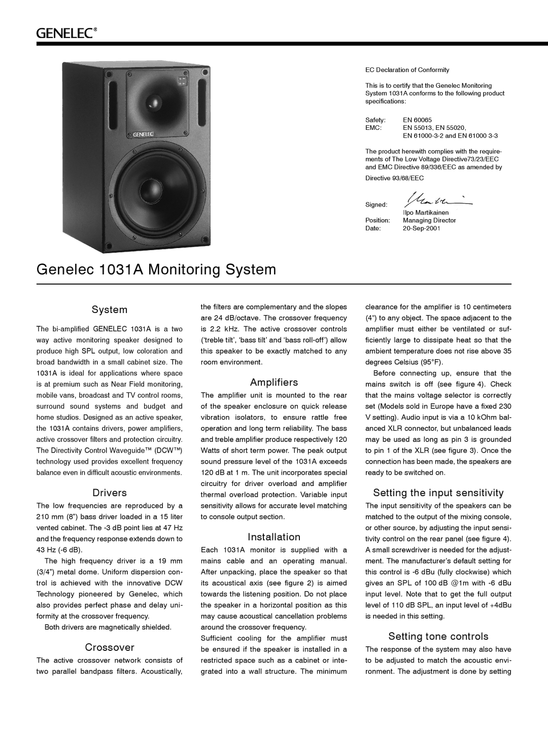
The low frequencies are reproduced by a 210 mm (8”) bass driver loaded in a 15 liter vented cabinet. The
The high frequency driver is a 19 mm (3/4”) metal dome. Uniform dispersion con- trol is achieved with the innovative DCW Technology pioneered by Genelec, which also provides perfect phase and delay uni- formity at the crossover frequency.
Both drivers are magnetically shielded.
Crossover
The active crossover network consists of two parallel bandpass filters. Acoustically,
the filters are complementary and the slopes are 24 dB/octave. The crossover frequency is 2.2 kHz. The active crossover controls (‘treble tilt’, ‘bass tilt’ and ‘bass
Amplifiers
The amplifier unit is mounted to the rear of the speaker enclosure on quick release vibration isolators, to ensure rattle free operation and long term reliability. The bass and treble amplifier produce respectively 120 Watts of short term power. The peak output sound pressure level of the 1031A exceeds 120 dB at 1 m. The unit incorporates special circuitry for driver overload and amplifier thermal overload protection. Variable input sensitivity allows for accurate level matching to console output section.
Installation
Each 1031A monitor is supplied with a mains cable and an operating manual. After unpacking, place the speaker so that its acoustical axis (see figure 2) is aimed towards the listening position. Do not place the speaker in a horizontal position as this may cause acoustical cancellation problems around the crossover frequency.
Sufficient cooling for the amplifier must be ensured if the speaker is installed in a restricted space such as a cabinet or inte- grated into a wall structure. The minimum
clearance for the amplifier is 10 centimeters (4") to any object. The space adjacent to the amplifier must either be ventilated or suf- ficiently large to dissipate heat so that the ambient temperature does not rise above 35 degrees Celsius (95°F).
Before connecting up, ensure that the mains switch is off (see figure 4). Check that the mains voltage selector is correctly set (Models sold in Europe have a fixed 230 V setting). Audio input is via a 10 kOhm bal- anced XLR connector, but unbalanced leads may be used as long as pin 3 is grounded to pin 1 of the XLR (see figure 3). Once the connection has been made, the speakers are ready to be switched on.
Setting the input sensitivity
The input sensitivity of the speakers can be matched to the output of the mixing console, or other source, by adjusting the input sensi- tivity control on the rear panel (see figure 4). A small screwdriver is needed for the adjust- ment. The manufacturer’s default setting for this control is
Setting tone controls
The response of the system may also have to be adjusted to match the acoustic envi- ronment. The adjustment is done by setting
