QT06024ANAX, QT06024AVSX, QT06024ANSX, QT06024AVAX specifications
The Generac QT06024AVAX, QT06024ANSX, QT06024AVSX, and QT06024ANAX are powerful and versatile residential generators designed for those who want the peace of mind provided by reliable backup power. These models from Generac's Guardian Series are engineered for performance, efficiency, and ease of use, making them ideal solutions for homeowners looking to ensure uninterrupted power during outages.One of the standout features of these generators is their robust 60 kW capacity, which allows them to power essential home appliances, HVAC systems, and even larger electricity-demanding devices without a hitch. This capacity makes them suitable for medium to large homes, providing enough energy to keep daily operations running smoothly even during extended outages.
The QT series incorporates Generac's advanced Quiet-Test technology, which reduces noise levels during self-testing. This feature enables the generator to perform regular self-diagnostic tests at a much quieter decibel level, ensuring it does not disrupt the household during these checks. Additionally, the generators are designed with a weather-resistant enclosure, providing durability and protection against various environmental conditions.
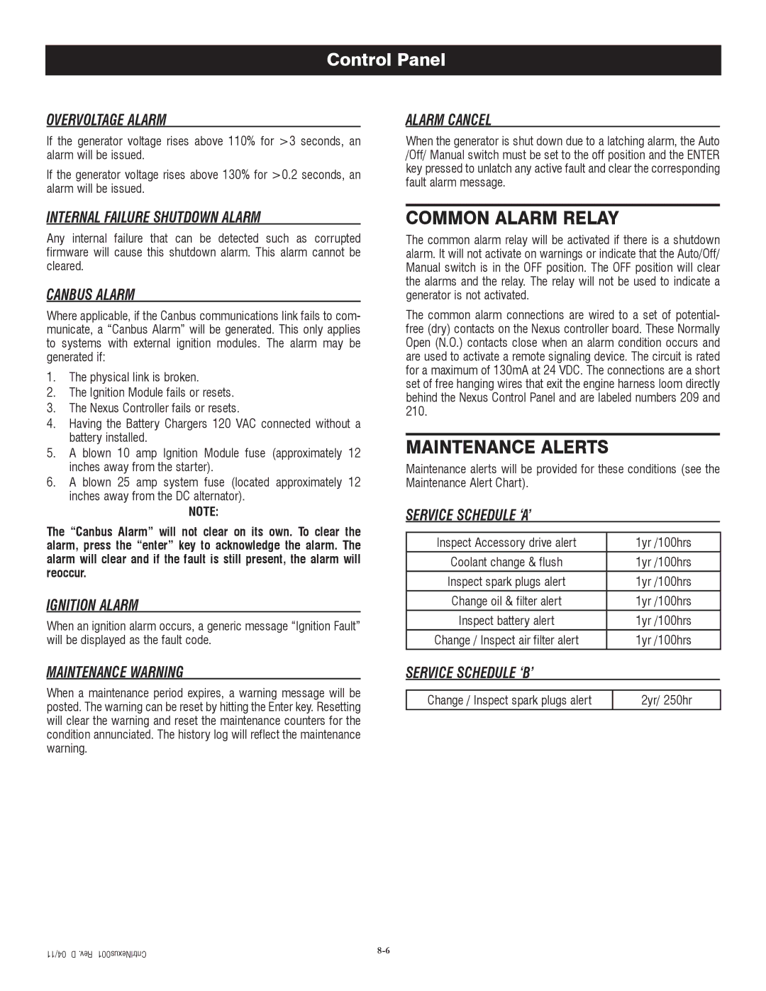
The models are equipped with an intuitive control panel featuring a user-friendly digital display that allows for easy monitoring of power usage and system status. They also feature an automatic transfer switch that seamlessly switches from grid power to generator power in case of an outage, ensuring that the transition is almost instantaneous and worry-free for homeowners.
Moreover, the QT series generators utilize a liquid-cooled engine, which provides greater efficiency and performance compared to air-cooled alternatives. This technology not only ensures longer run times but also contributes to a longer lifespan for the generator. The low-oil pressure shutdown feature is another critical safety aspect, protecting the engine from damage by automatically shutting it down when oil levels are too low.
Finally, these models are designed with flexibility in mind. They can be customized with various accessories and options to meet specific homeowner needs. Whether for full home backup or partial power, the Generac QT06024AVAX, QT06024ANSX, QT06024AVSX, and QT06024ANAX are reliable solutions that give homeowners the confidence to weather any storm without losing power. With their combination of advanced technology, powerful performance, and user-friendly features, Generac continues to set the standard in home standby power solutions.

