LP121HT specifications
The Giant LP121HT is a remarkable addition to the world of high-performance machinery, primarily designed for professionals in diverse industries such as construction, agriculture, and logistics. This versatile piece of equipment stands out due to its exceptional capabilities and modern technologies, making it a go-to choice for anyone looking to enhance productivity and efficiency on the job site.One of the defining features of the LP121HT is its powerful engine, which combines high torque with low fuel consumption. This results in not only impressive performance but also significant cost savings over time. The engine complies with stringent environmental regulations, ensuring that it meets requirements for emissions while delivering robust power.
The design of the LP121HT is tailored for optimal maneuverability and ease of use. Its compact size allows it to navigate tight spaces while providing a stable base for heavy lifting tasks. The operating platform is ergonomically designed, offering a comfortable experience for the operator. This includes intuitive controls that facilitate precision handling, reducing operator fatigue over long work periods.
Moreover, the LP121HT incorporates advanced hydraulic technologies that enable smooth lifting and lowering operations. This hydraulic system is designed for rapid cycle times, allowing for quick and efficient movements. With a maximum lifting capacity that exceeds many of its competitors, the LP121HT is capable of handling demanding loads with ease.
Another highlight of the LP121HT is its robust safety features. Equipped with an overload protection system, the machine prevents potential hazards by alerting the operator when the weight exceeds safe limits. Additionally, the sturdy chassis and low center of gravity enhance stability, minimizing the risk of tipping during operation.
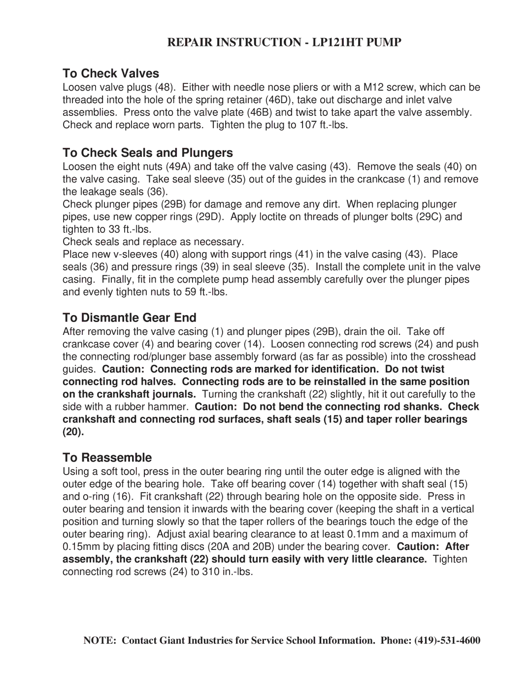
In terms of maintenance, the Giant LP121HT has been designed for user convenience. Key components are easily accessible, reducing downtime and simplifying routine checks. The use of high-quality materials ensures durability, allowing the machine to withstand the rigors of tough job environments.
Lastly, the LP121HT is compatible with a variety of attachments, increasing its versatility. Whether it is lifting pallets, transporting materials, or performing landscaping tasks, this machine adapts to the needs of various applications.
In conclusion, the Giant LP121HT, with its powerful engine, advanced hydraulic system, ergonomic design, and extensive safety features, is an exceptional tool that enhances operational efficiency across multiple industries. It is engineered to meet the demands of modern work environments, making it an indispensable asset for any professional.
