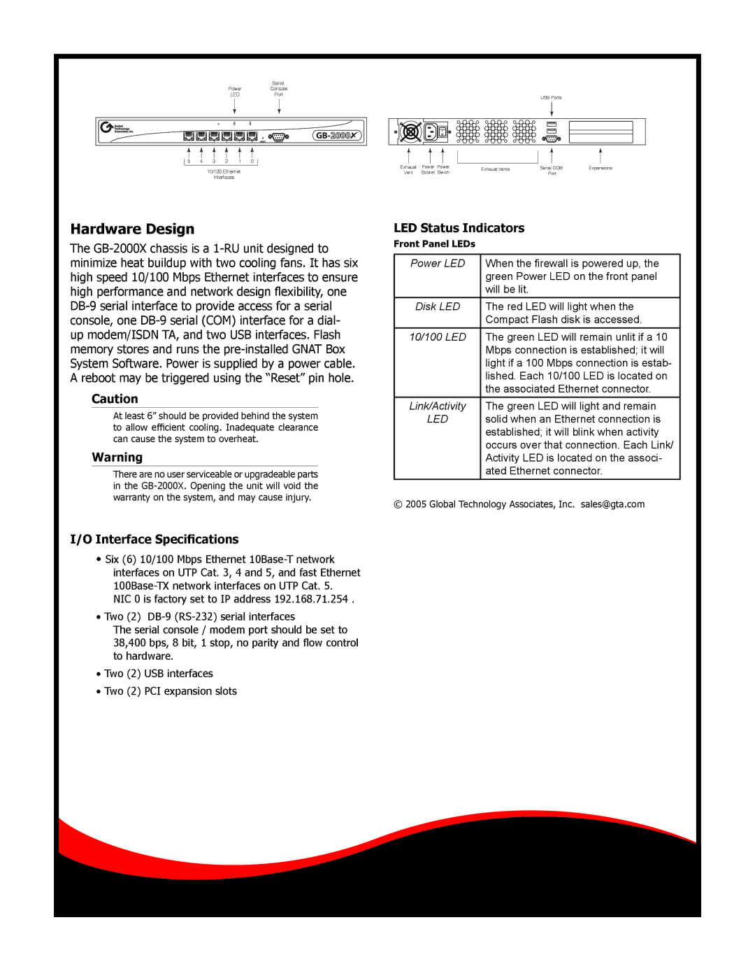
GB-2000X specifications
Global Technology Associates has made a significant mark in the tech industry with its flagship product, the GB-2000X. This versatile system offers a unique blend of advanced features, innovative technologies, and exceptional characteristics that cater to a wide range of user needs.At the heart of the GB-2000X is its powerful processing capability, driven by the latest multi-core architecture. This ensures rapid data processing and responsiveness, making it ideal for demanding applications across various sectors, from finance to healthcare. With a customizable configuration, users can select from a range of CPU options tailored to their specific performance requirements.
The GB-2000X is equipped with state-of-the-art connectivity options, including multiple USB 3.0 ports, Thunderbolt interfaces, and support for both Wi-Fi 6 and Ethernet 10G. This versatility enables seamless integration into existing networks and enhances data transfer speeds, facilitating a smooth workflow. Additionally, the device supports Bluetooth 5.0 for efficient wireless connection to peripherals.
Another standout feature of the GB-2000X is its advanced security protocols. It incorporates biometric authentication, encryption capabilities, and multi-factor authentication, ensuring that sensitive information remains protected against unauthorized access. This is particularly crucial for industries that deal with confidential data, such as banking and healthcare.
The device boasts an impressive multimedia experience too, with high-resolution displays and superior audio systems. The GB-2000X supports 4K resolution and various HDR formats, making it an excellent choice for content creators and multimedia professionals. Additionally, its audio capabilities are enhanced by built-in noise-cancellation and surround sound technology for an immersive listening experience.
Battery life is another area where the GB-2000X excels. With energy-efficient components and smart power management, users can expect extended operational time, making it suitable for on-the-go professionals.
Overall, the Global Technology Associates GB-2000X combines performance, security, connectivity, and multimedia capabilities into a single, robust system. Its adaptability and advanced features make it a frontrunner in its class, appealing to a diverse array of users who demand reliability and performance in today's fast-paced digital environment. Whether for work or play, the GB-2000X stands ready to meet the challenges of modern technology head-on.

