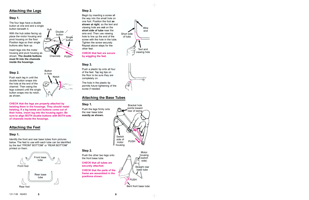
1444, 1435 specifications
Graco, a well-known name in the realm of fluid management and spray technology, offers a range of professional-grade products designed for various applications. Among its stellar lineup, the Graco 1435 and Graco 1444 stand out as reliable choices for users requiring quality performance in their projects.The Graco 1435 is engineered for durability and efficiency. One of its main features is the powerful motor, which delivers consistent pressure and unmatched output for a variety of painting and finishing applications. The unit comes equipped with a robust pump that can handle both water-based and solvent-based materials, enhancing versatility and usability across different projects. Its lightweight design facilitates easy transport without sacrificing stability, making it an ideal companion on job sites. Additionally, the Graco 1435 integrates an easy-to-read pressure gauge, allowing users to monitor and adjust settings on the fly, resulting in optimal results with minimal effort.
On the other hand, the Graco 1444 is designed for larger projects and professionals who demand high productivity. It boasts an advanced pumping system that ensures smooth and consistent material flow, significantly reducing the risk of clogs and interruptions. The Graco 1444 features heavy-duty construction, making it capable of withstanding harsh environments while still delivering exceptional performance. This model incorporates Graco’s proprietary technology that helps to reduce overspray, ensuring a cleaner working environment and more efficient material usage. An adjustable pressure control system provides the flexibility required for various coatings and surface types.
Both models benefit from Graco's commitment to user-friendly design, with straightforward setup processes and easy maintenance features. They come with comprehensive manuals and support to help users get the most out of their equipment. Furthermore, Graco’s innovative engineering ensures that both the 1435 and 1444 models can withstand the rigors of professional use, minimizing downtime and enhancing productivity.
In conclusion, the Graco 1435 and 1444 models are excellent choices for professionals looking for reliable, durable, and efficient painting solutions. With their advanced features and technologies, these units provide the performance needed to tackle any painting job, making them valuable assets in any toolkit. Whether for small projects or large-scale applications, both models exemplify Graco's dedication to quality and innovation in the field of spray equipment.

