Manuals
/
Graco
/
Personal Care
/
Personal Lift
Graco
204121, 204124 Installation, Locating the Elevator Fig, Installing the Elevator Fig
Models:
204121
1
3
8
8
Download
8 pages
12.97 Kb
1
2
3
4
5
6
7
8
Install
Parts list
Warranty
Maintenance
Adjusting the Elevator Speed
Page 3
Image 3
Page 2
Page 4
Page 3
Image 3
Page 2
Page 4
Contents
306522F
Instructions-Parts List
Important Safety Instructions
Air Operated Pump Elevator
Caution Symbol
Table of Contents
Symbols
Warning Symbol
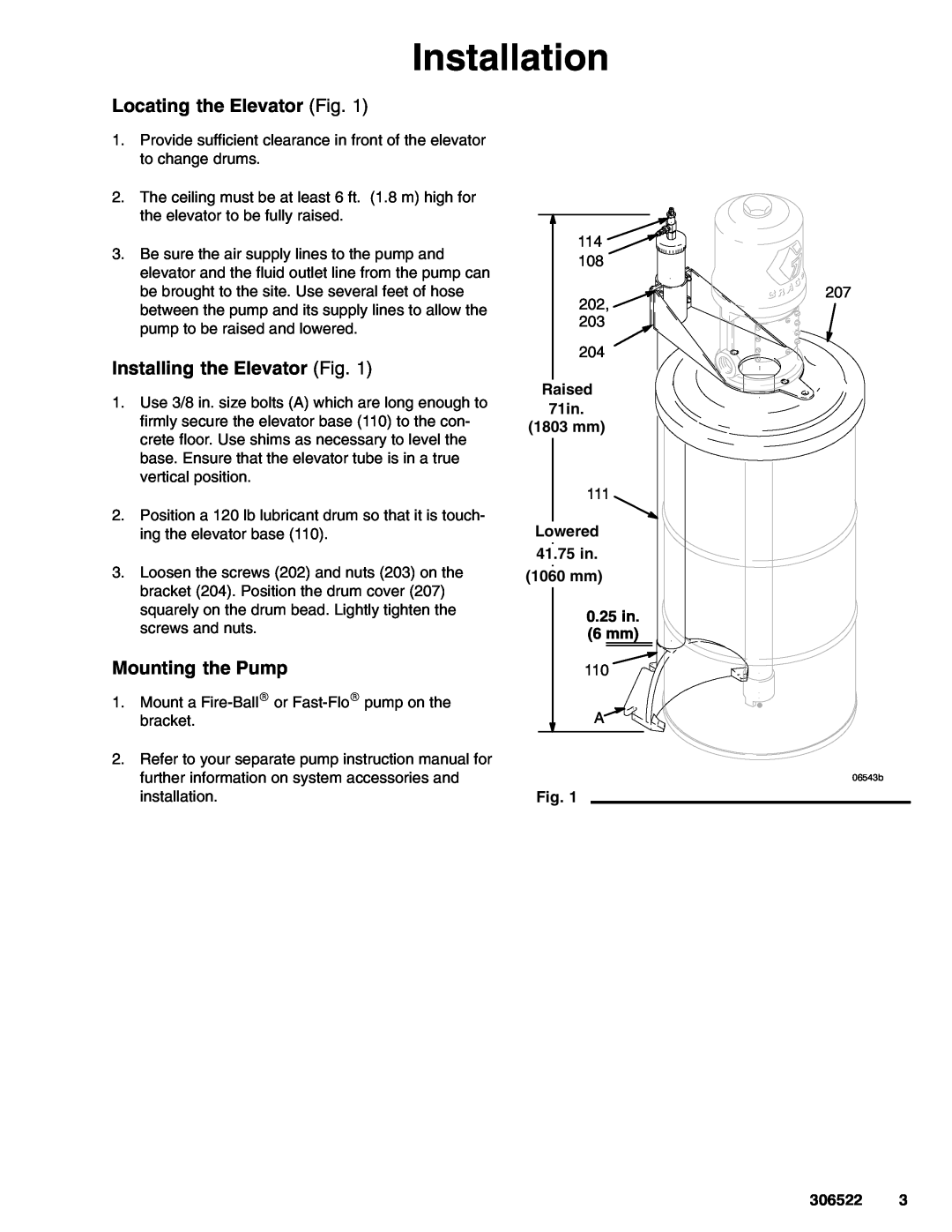
Mounting the Pump
Installation
Installing the Elevator Fig
Locating the Elevator Fig
Changing Drums
Adjusting the Elevator Speed
Operation
Raising and Lowering the Pump
Lubrication Fig
Maintenance
Ref No. 1 Elevator
Ref No. 114, 203743 Restrictor Valve Assembly Includes items 301 to
Parts
Model Elevator Cover and Bracket
Description
Ref No. 114 Restrictor Valve Assembly
Model Pump Elevator, Cover, and Bracket
Ref No. 2 Drum Cover & Bracket
Graco reserves the right to make changes at any time without notice
The Graco Standard Warranty
Graco Information
FOR GRACO CANADA CUSTOMERS
Top
Page
Image
Contents