Manuals
/
Graco
/
Power Tools
/
Paint Sprayer
Graco
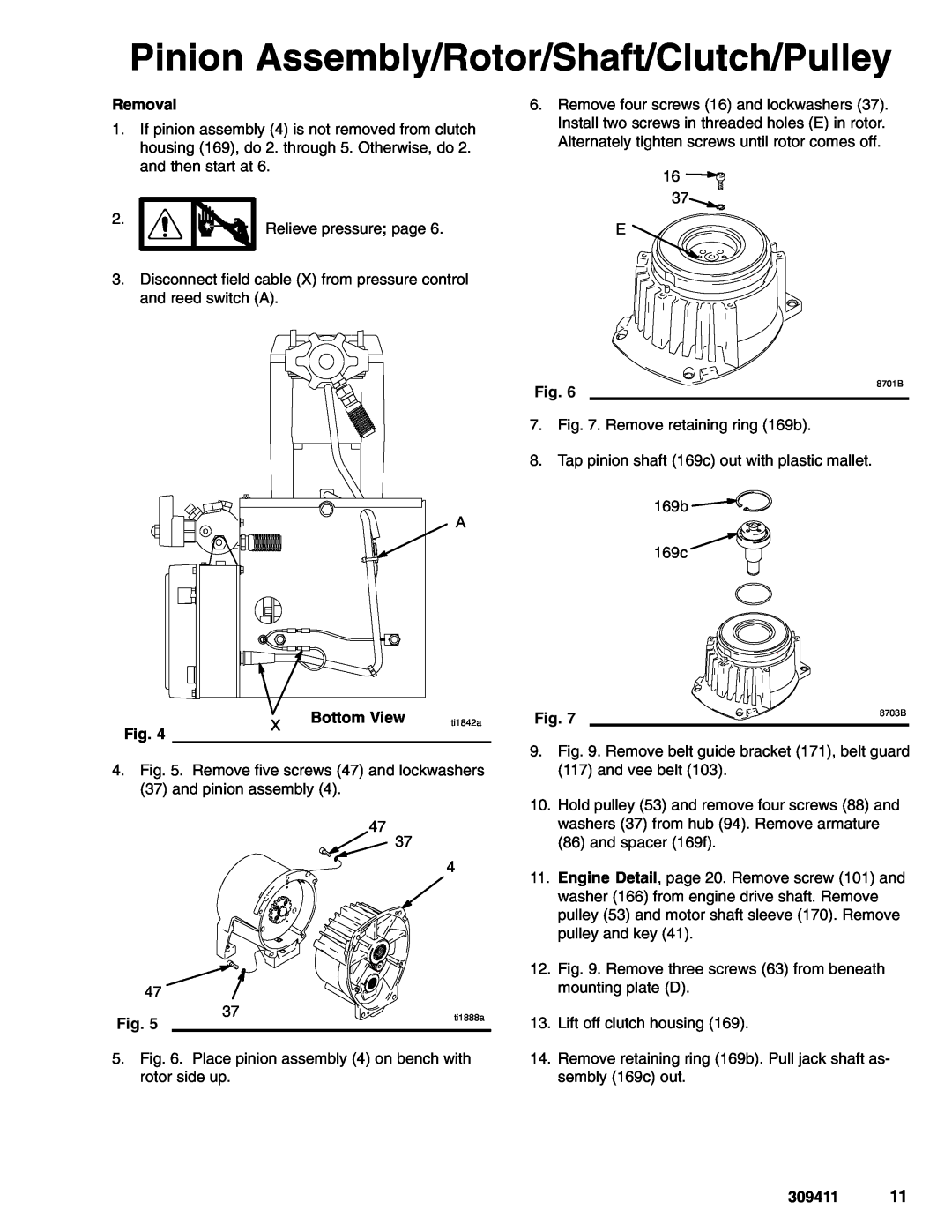
233713 Pinion Assembly/Rotor/Shaft/Clutch/Pulley, Bottom View, Removal, 309411, ti1842a
Models:
233711
1
11
26
26
Download
26 pages
61.3 Kb
8
9
10
11
12
13
14
15
Troubleshooting
Install
Parts list
Warranty
Dimension
Maintenance
Pressure Adjust Potentiometer
Displacement Pump
Pump On/Off Switch
Drive Housing
Page 11
Image 11
Page 10
Page 12
Page 11
Image 11
Page 10
Page 12
Contents
This manual contains important
INSTRUCTIONS-PARTS LIST
5.5 HORSEPOWER, GASOLINE POWERED
GRACO INC. P.O. BOX 1441 MINNEAPOLIS, MN
Warnings and Cautions
Table of Contents
Warning Symbol
Caution Symbol
309411
SKIN INJECTION HAZARD
TOXIC FLUID HAZARD
RECOIL HAZARD
EQUIPMENT MISUSE HAZARD
HAZARD OF USING FLUIDS CONTAINING HALOGENATED HYDROCARBONS
FIRE AND EXPLOSION HAZARD
Engine On/Off Switch
Spray Gun Trigger Lock
Reference your Spray Gun Manual
Pump On/Off Switch
INJECTION HAZARD
Maintenance
Pressure Relief Procedure
CAUSE
Troubleshooting
PROBLEM
SOLUTION
Thin fluid according to supplier’s recommenda
Use larger diameter hose and/or reduce overall
1 B
Bearing Housing and Connecting Rod
Installation
Removal
Drive Housing
ti1888a
Pinion Assembly/Rotor/Shaft/Clutch/Pulley
Bottom View
ti1842a
ti1853a
17. Page 10. Do Drive Housing, Installation
0.12 ±.01 in. 3.0 ±.25 mm
ti1849a
On/Off Switch
Pressure Control Transducer
Pressure Adjust Potentiometer
Pressure Control
Control Board
DISPLAY
After a fault, follow these steps to restart sprayer
Pressure Control Repair
Digital Display Messages
Repair
Displacement Pump
309411
Model 233709, Series A
Parts - Basic Sprayer
HOUSING, bearing
HOUSING, drive
HOUSING, pinion
PUMP, displacement
ti1846a
Engine Detail
Ref No. 4 and
Parts List & Drawing - Pinion Assembly
Ref No. 4 Pinion Housing Assembly
Ref No. 3 Drive Housing Assembly
Parts Drawing - Sprayer
Ref No Pressure Control Assembly
ON/OFF SWITCH DRIVE HOUSING PINION HOUSING CONTROL BOARD TRANSDUCER
Parts List - Sprayer
VIEW A
Pressure Control DISPLAY BOARD Wiring Diagram
Contractor II Gun Kit
Parts List & Drawing -Clutch Assembly
Parts - Complete Sprayer
Model 233710
DANGER LABELS
Technical Data
Dimensions
Parts - Lo-Boy Suction Set Kit
reserves right to make changes at any time without notice
Graco Standard Warranty
distributor near you1-800-690-2894 Toll Free
FOR GRACO CANADA CUSTOMERS
Top
Page
Image
Contents