Setup
KEY
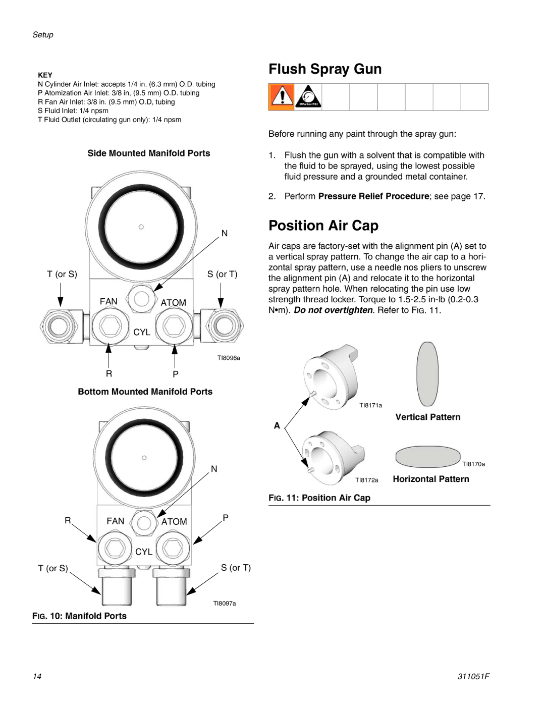
N Cylinder Air Inlet: accepts 1/4 in. (6.3 mm) O.D. tubing
P Atomization Air Inlet: 3/8 in, (9.5 mm) O.D. tubing
R Fan Air Inlet: 3/8 in. (9.5 mm) O.D, tubing
S Fluid Inlet: 1/4 npsm
T Fluid Outlet (circulating gun only): 1/4 npsm
Side Mounted Manifold Ports
N
T (or S) | S (or T) |
FAN ATOM
CYL
TI8096a
RP
Bottom Mounted Manifold Ports
N
R | FAN | ATOM | P |
| |||
|
| CYL |
|
T (or S) |
|
| S (or T) |
|
|
| TI8097a |
FIG. 10: Manifold Ports
Flush Spray Gun
Before running any paint through the spray gun:
1.Flush the gun with a solvent that is compatible with the fluid to be sprayed, using the lowest possible fluid pressure and a grounded metal container.
2.Perform Pressure Relief Procedure; see page 17.
Position Air Cap
Air caps are
TI8171a
Vertical Pattern
A
TI8170a
TI8172a Horizontal Pattern
FIG. 11: Position Air Cap
14 | 311051F |