Graco 965124, 965129 important safety instructions Typical Installation

Models: 965129 965124

1 18
Download 18 pages 51.93 Kb
Page 6
Image 6
Typical Installation

Installation

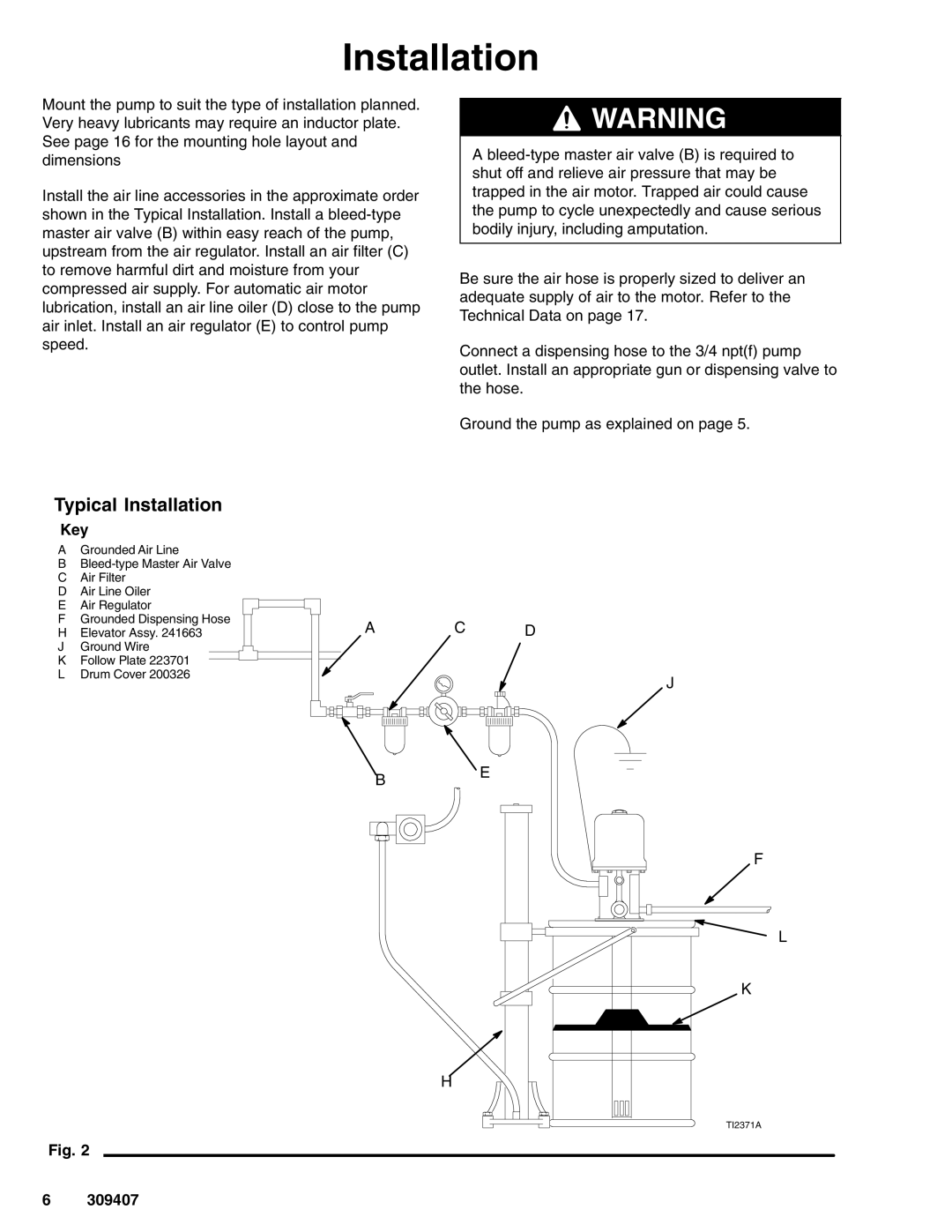
Mount the pump to suit the type of installation planned. Very heavy lubricants may require an inductor plate. See page 16 for the mounting hole layout and dimensions

Install the air line accessories in the approximate order shown in the Typical Installation. Install a bleed-type master air valve (B) within easy reach of the pump, upstream from the air regulator. Install an air filter (C) to remove harmful dirt and moisture from your compressed air supply. For automatic air motor lubrication, install an air line oiler (D) close to the pump air inlet. Install an air regulator (E) to control pump speed.

Manual background WARNING

A bleed-type master air valve (B) is required to shut off and relieve air pressure that may be trapped in the air motor. Trapped air could cause the pump to cycle unexpectedly and cause serious bodily injury, including amputation.

Be sure the air hose is properly sized to deliver an adequate supply of air to the motor. Refer to the Technical Data on page 17.

Connect a dispensing hose to the 3/4 npt(f) pump outlet. Install an appropriate gun or dispensing valve to the hose.

Ground the pump as explained on page 5.

Typical Installation

Key

AGrounded Air Line

BBleed-type Master Air Valve

CAir Filter

DAir Line Oiler

EAir Regulator

FGrounded Dispensing Hose

HElevator Assy. 241663

JGround Wire

KFollow Plate 223701

LDrum Cover 200326

Fig. 2

A C D

J

BE

F

L

K

H

TI2371A

6 309407

Page 6
Image 6
Graco 965124, 965129 important safety instructions Typical Installation