Pressure Relief Procedure
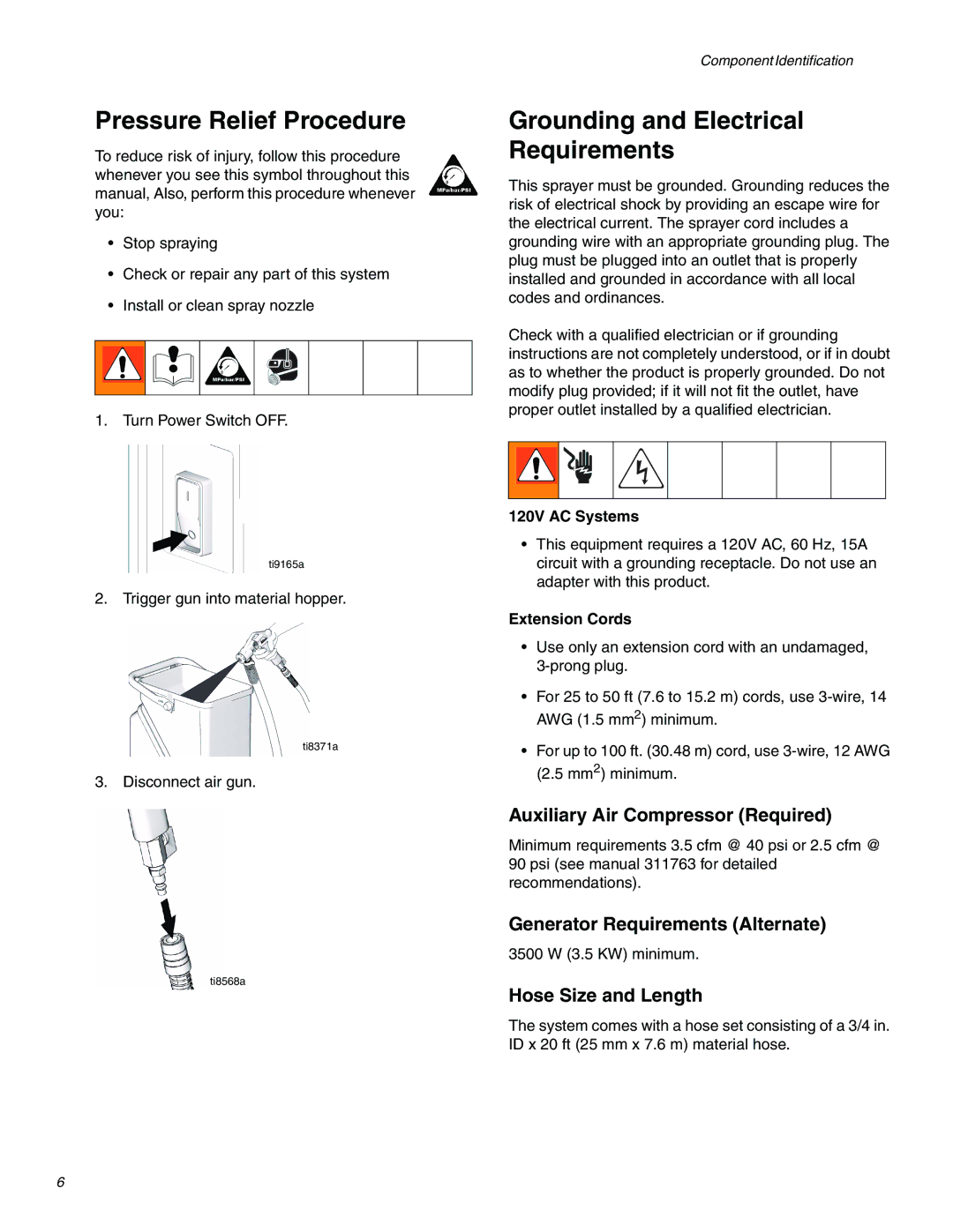
To reduce risk of injury, follow this procedure whenever you see this symbol throughout this manual, Also, perform this procedure whenever you:
•Stop spraying
•Check or repair any part of this system
•Install or clean spray nozzle
1.Turn Power Switch OFF.
ti9165a
2. Trigger gun into material hopper.
ti8371a
3. Disconnect air gun.
ti8568a
Component Identification
Grounding and Electrical Requirements
This sprayer must be grounded. Grounding reduces the risk of electrical shock by providing an escape wire for the electrical current. The sprayer cord includes a grounding wire with an appropriate grounding plug. The plug must be plugged into an outlet that is properly installed and grounded in accordance with all local codes and ordinances.
Check with a qualified electrician or if grounding instructions are not completely understood, or if in doubt as to whether the product is properly grounded. Do not modify plug provided; if it will not fit the outlet, have proper outlet installed by a qualified electrician.
120V AC Systems
•This equipment requires a 120V AC, 60 Hz, 15A circuit with a grounding receptacle. Do not use an adapter with this product.
Extension Cords
•Use only an extension cord with an undamaged,
•For 25 to 50 ft (7.6 to 15.2 m) cords, use
•For up to 100 ft. (30.48 m) cord, use
Auxiliary Air Compressor (Required)
Minimum requirements 3.5 cfm @ 40 psi or 2.5 cfm @ 90 psi (see manual 311763 for detailed recommendations).
Generator Requirements (Alternate)
3500 W (3.5 KW) minimum.
Hose Size and Length
The system comes with a hose set consisting of a 3/4 in. ID x 20 ft (25 mm x 7.6 m) material hose.
6
