Installation
Installation
1.Install one regulator for each spray gun.
2.Apply thread sealant to connections as necessary.
3.Make sure that the direction of fluid flow agrees with the flow direction markings on the regulator body.
a.Install a fluid pressure regulator upstream of the gun: Connect the fluid line from the pump to the inlet of the fluid regulator. Connect the fluid line to the gun to the regulator’s outlet.
b.Install a back pressure regulator downstream of the gun. Connect the fluid return line from the gun to the inlet of the back pressure regulator. Connect the fluid return line to the pump to the regulator’s outlet.
4.Flush and test the entire system.
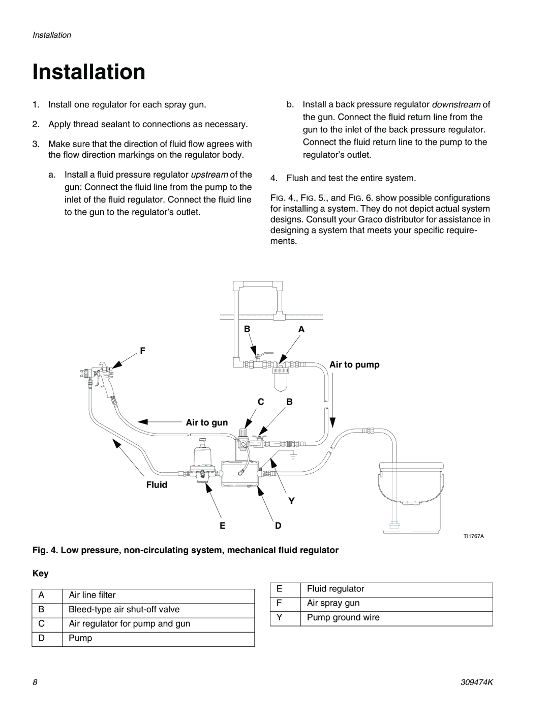
FIG. 4., FIG. 5., and FIG. 6. show possible configurations for installing a system. They do not depict actual system designs. Consult your Graco distributor for assistance in designing a system that meets your specific require- ments.
F
 Air to gun
Fluid
E
BA
Air to pump
C B
Y
D
TI1767A
Fig. 4. Low pressure, non-circulating system, mechanical fluid regulator
Key
AAir line filter
B
CAir regulator for pump and gun
DPump
EFluid regulator
FAir spray gun
Y | Pump ground wire |
8 | 309474K |