CHEMICAL |
| / | ADJUSTABLE |
|
STORAGE TRAY |
| NOZZLE |
| |
\ |
|
|
|
|
PUMP OIL LEVEL |
|
|
|
|
INDICATOR |
|
|
|
|
WINDOW |
| SPRAY |
| |
|
|
| ||
|
|
| GUN |
|
|
|
| QUICK | , |
|
| COUPLER \ | ||
MOTOR |
| HIGH PRESSURE |
| |
| SPRAY |
|
| |
SWITCH |
|
|
|
|
I | ’ | TWO CHEMICAL |
|
|
| SELECTOR VALVE |
|
| |
CHEMICAL |
|
|
|
|
METERING VALVE |
|
|
|
|
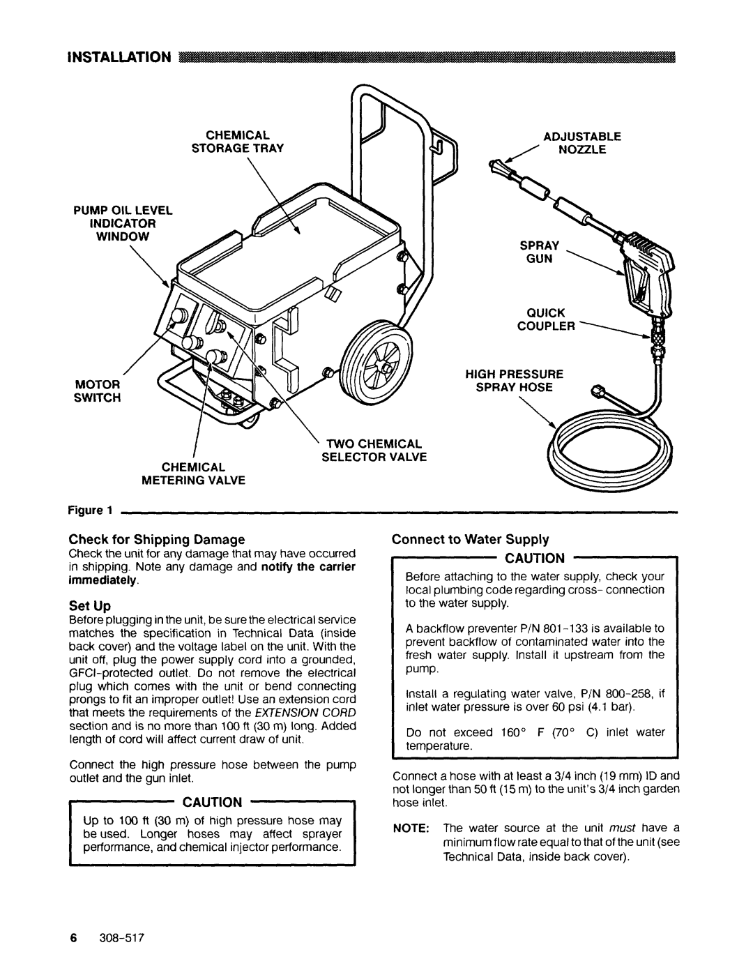
Check for Shipping Damage
Check the unit for any damage that may have occurred in shipping. Note any damage and notify the carrier immediately.
Set Up
Before plugging in the unit, be sure the electrical service matches the specification in Technical Data (inside back cover) and the voltage label on the unit. With the unit off, plug the power supply cord into a grounded,
Connect the high pressure hose between the pump outlet and the gun inlet.
CAUTION
Up to 100 ft (30 m) of high pressure hose may be used. Longer hoses may affect sprayer r- performance, and chemical injector performance.
Connect to Water Supply
CAUTION
Before attaching to the water supply, check your local plumbing code regarding cross- connection to the water supply.
A backflow preventer P/N
pump.
Install a regulating water valve, P/N
Do not exceed 160” F (70” C) inlet water temperature.
Connect a hose with at least a 3/4 inch (19 mm) ID and not longer than 50 ft (15 m) to the unit’s 3/4 inch garden hose inlet.
NOTE: The water source at the unit must have a minimum flow rate equal to that of the unit (see Technical Data, inside back cover).
6