Repair
Disassembly
1.Follow Pressure Relief Procedure. Engage trigger lock.
2.Disconnect fluid hose. Remove RAC tip guard and
tip (19 and
3.Using a wrench, remove the cap (4) with spring (5) (releases spring tension on needle).
4.Remove the valve seat (10) and gasket (9).
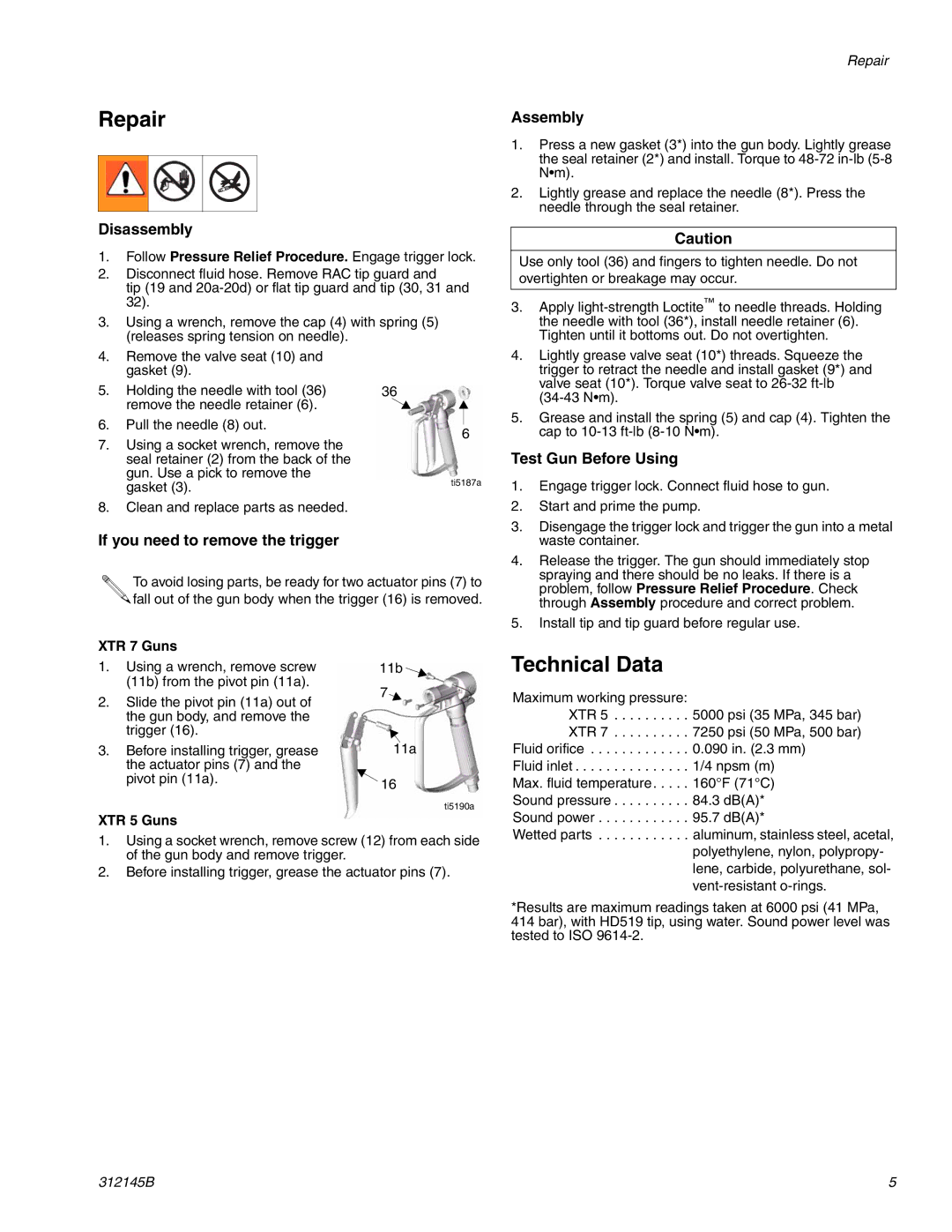
5. | Holding the needle with tool (36) | 36 |
| |
| remove the needle retainer (6). |
|
| |
|
|
| ||
6. | Pull the needle (8) out. |
|
| |
6 | ||||
|
| |||
7.Using a socket wrench, remove the seal retainer (2) from the back of the gun. Use a pick to remove the
gasket (3). | ti5187a |
|
8.Clean and replace parts as needed.
If you need to remove the trigger
To avoid losing parts, be ready for two actuator pins (7) to ![]()
![]() fall out of the gun body when the trigger (16) is removed.
fall out of the gun body when the trigger (16) is removed.
Repair
Assembly
1.Press a new gasket (3*) into the gun body. Lightly grease the seal retainer (2*) and install. Torque to
2.Lightly grease and replace the needle (8*). Press the needle through the seal retainer.
Caution
Use only tool (36) and fingers to tighten needle. Do not overtighten or breakage may occur.
3.Apply
4.Lightly grease valve seat (10*) threads. Squeeze the trigger to retract the needle and install gasket (9*) and valve seat (10*). Torque valve seat to
5.Grease and install the spring (5) and cap (4). Tighten the cap to
Test Gun Before Using
1.Engage trigger lock. Connect fluid hose to gun.
2.Start and prime the pump.
3.Disengage the trigger lock and trigger the gun into a metal waste container.
4.Release the trigger. The gun should immediately stop spraying and there should be no leaks. If there is a problem, follow Pressure Relief Procedure. Check through Assembly procedure and correct problem.
5.Install tip and tip guard before regular use.
XTR 7 Guns
1.Using a wrench, remove screw (11b) from the pivot pin (11a).
2.Slide the pivot pin (11a) out of the gun body, and remove the trigger (16).
3.Before installing trigger, grease the actuator pins (7) and the pivot pin (11a).
XTR 5 Guns
11b ![]()
7![]()
11a
16
ti5190a
Technical Data
Maximum working pressure:
XTR 5 . . . . . . . . . . 5000 psi (35 MPa, 345 bar) XTR 7 . . . . . . . . . . 7250 psi (50 MPa, 500 bar)
Fluid orifice . . . . . . . . . . . . . 0.090 in. (2.3 mm) Fluid inlet . . . . . . . . . . . . . . . 1/4 npsm (m) Max. fluid temperature . . . . . 160°F (71°C) Sound pressure . . . . . . . . . . 84.3 dB(A)* Sound power . . . . . . . . . . . . 95.7 dB(A)*
1.Using a socket wrench, remove screw (12) from each side of the gun body and remove trigger.
2.Before installing trigger, grease the actuator pins (7).
Wetted parts . . . . . . . . . . . . aluminum, stainless steel, acetal, polyethylene, nylon, polypropy- lene, carbide, polyurethane, sol-
*Results are maximum readings taken at 6000 psi (41 MPa, 414 bar), with HD519 tip, using water. Sound power level was tested to ISO
312145B | 5 |