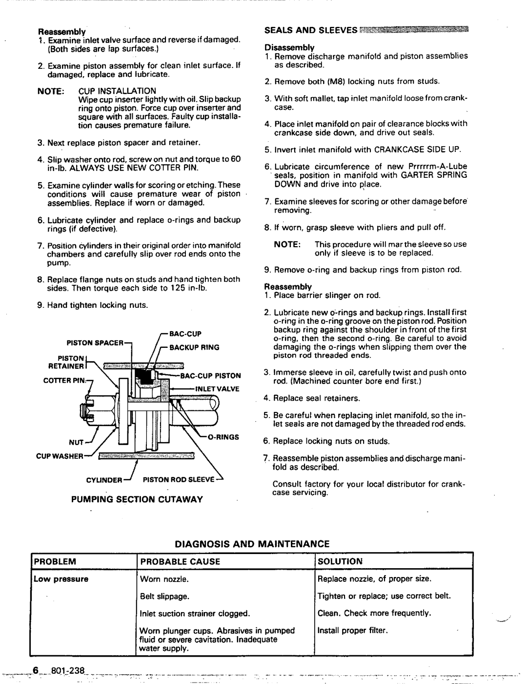
1204E, 801-238, 800-051 specifications
Graco Inc. is a globally recognized brand in fluid handling, offering a diverse range of products characterized by durability, efficiency, and innovative technology. Among its extensive product line, the Graco Inc. models 1204E, 801-238, and 800-051 stand out due to their unique features and robust design, making them essential tools in various industrial applications.The Graco Inc. 1204E is an advanced air-operated double diaphragm pump known for its exceptional performance and reliability. This model is built with high-quality materials that ensure longevity even in demanding environments. One of its main features is the ability to handle a wide range of fluids, including thick and abrasive materials. The 1204E utilizes a control system that maximizes efficiency by adjusting flow rates automatically, leading to reduced operational costs and improved productivity. Furthermore, its compact design allows for easy installation in tight spaces, making it a versatile choice for numerous applications.
The 801-238 model is a high-performance grease pump specifically designed for reliable lubrication. This pump is equipped with a user-friendly interface and a powerful motor that contributes to its impressive output capabilities. Its robust construction allows it to withstand harsh conditions, ensuring that maintenance tasks can be performed with minimal downtime. A standout feature of the 801-238 is its integrated monitoring system, which provides real-time feedback on pump performance, helping operators to ensure optimal efficiency and identify potential issues before they escalate.
Lastly, the 800-051 represents Graco's commitment to precision and reliability in paint application. This model is engineered to deliver a consistent spray pattern, allowing for a flawless finish every time. The 800-051 incorporates advanced technology that minimizes overspray and waste, making it both an economical and environmentally friendly option. Additionally, its ergonomic design ensures ease of use, which is especially beneficial for long hours of operation.
In conclusion, the Graco Inc. models 1204E, 801-238, and 800-051 highlight the company's dedication to innovation and quality. Each model features technologies that enhance usability and efficiency, ensuring they meet the diverse needs of their users in industrial settings. With Graco's reputation for excellence, these products continue to set the standard in their respective fields.

