SECTION I
INTRODUCTION AND DESCRIPTION
1-1 Introduction
We are pleased to have you as a PECO customer. Your collection system has been designed to give you a low maintenance, simple, and effective way to collect the grass clippings from your mower. This manual is provided to give you the necessary instructions to properly mount and operate the collection system on your mower. Please read this manual thoroughly. Understand what each control is for and how to use it. Observe all safety decal precautions on the machine and noted throughout the manual.
Note: all references made to right, left, front, rear, top or bottom are as viewed from the normal operator’s position on the mower.
1-2 Description
The collection system is designed for turf maintenance where there is a need to collect the grass clippings as the mower cuts the turf. It is also good for picking up leaves and twigs in
The engine/blower/blade assembly, is mounted on the right side of the unit. The blower draws grass clippings from the discharge area of the cutter deck up to the aluminum container mounted over the rear portion of the frame. The operator can engage the engine/blower/blade assembly by starting the engine. Once the container is full of clippings, the operator can easily push and raise the lift handle, releasing the container’s rear door and the container will pivot towards the ground.
Section II INSTALLATION FOR USE
2-1 Preparation Of Mower
Carefully dismantle wooden shipping crate from around the components. Cut retaining straps and separate the parts. The collection system will have various parts located inside. Remove and sort all parts for easy identification.
NOTE: before each step of assembly it will help to study the exploded drawings on pages 7 and 8.
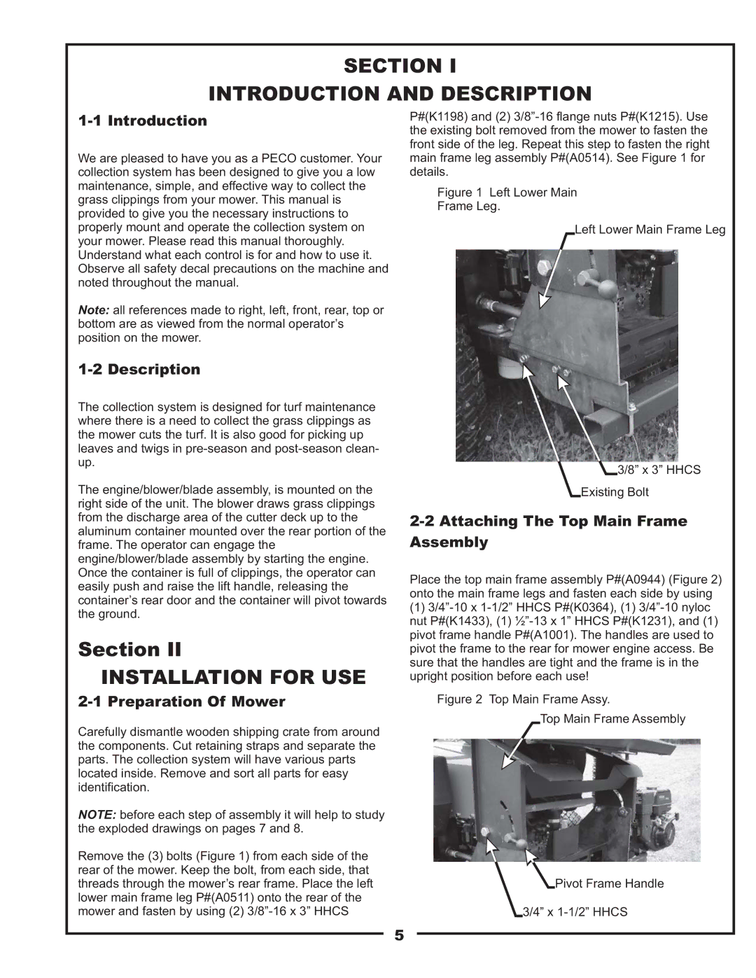
Remove the (3) bolts (Figure 1) from each side of the rear of the mower. Keep the bolt, from each side, that threads through the mower’s rear frame. Place the left lower main frame leg P#(A0511) onto the rear of the mower and fasten by using (2)
P#(K1198) and (2)
Figure 1 Left Lower Main
Frame Leg.
Left Lower Main Frame Leg
3/8” x 3” HHCS
Existing Bolt
2-2 Attaching The Top Main Frame Assembly
Place the top main frame assembly P#(A0944) (Figure 2) onto the main frame legs and fasten each side by using
(1)
Figure 2 Top Main Frame Assy.
Top Main Frame Assembly
Pivot Frame Handle
3/4” x 1-1/2” HHCS
5