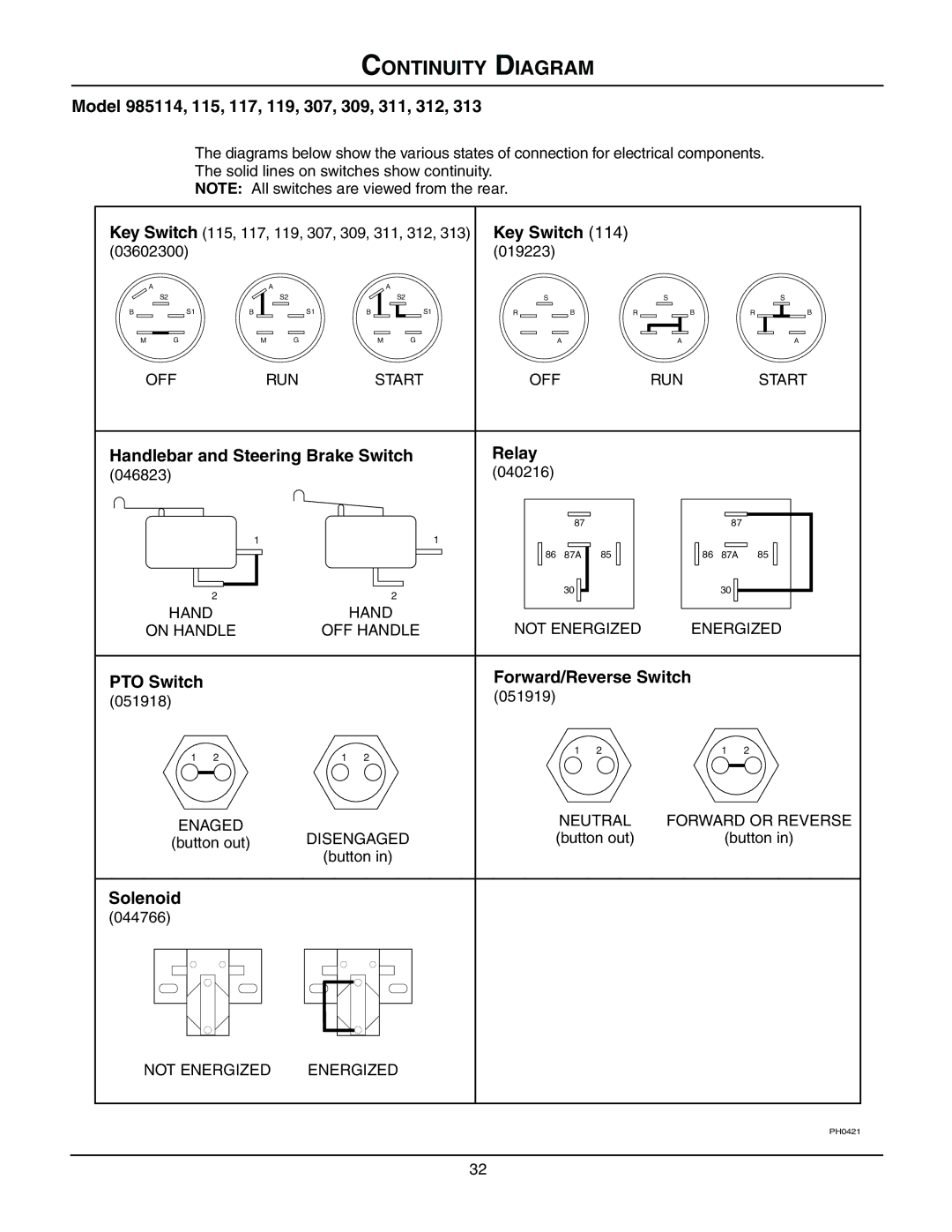
08499200B, 985313, 985311, 985309, 985307 specifications
The Gravely 985114, 985115, 985117, 985119, and 985312 models are part of Gravely's renowned lineup of commercial-grade zero-turn lawn mowers, designed specifically to offer precision, power, and efficiency for landscaping professionals and serious homeowners alike. These models incorporate advanced engineering and thoughtful design, catering to various mowing needs and ensuring superior performance.The Gravely 985114 model is equipped with a robust 48-inch cutting deck, making it ideal for residential and light commercial use. Its powerful engine delivers reliable performance, allowing users to tackle various terrains with ease. The intuitive controls ensure smooth maneuverability, helping to achieve a clean and precise cut every time.
Moving up the range, the Gravely 985115 features a wider 52-inch cutting deck, which enhances productivity by covering more ground in less time. This model is perfect for tackling larger properties or commercial sites. With its heavy-duty construction, users can expect durability and longevity even under demanding conditions. The adjustable cutting height adds versatility, allowing operators to achieve their desired grass length.
The Gravely 985117 takes performance to the next level with a powerful engine and a 60-inch cutting deck. This model is engineered for heavy-duty commercial use, ensuring that both efficiency and performance are optimized. The high-quality blades ensure a clean cut, while the robust frame can withstand continuous use.
For even more capability, the Gravely 985119 model offers cutting-edge technology, incorporating advanced cooling systems that prolong engine life and enhance performance during extended mowing sessions. This model also features an ergonomic design, making it comfortable for operators to navigate.
The Gravely 985312 model stands out with its innovative features, including a suspension system that minimizes vibrations, which significantly improves user comfort. Its high-capacity fuel tank allows for longer operation times without frequent refueling, making it an excellent choice for larger jobs.
All models in this series are built with a heavy-duty steel frame and commercial-grade components, ensuring they can handle the toughest of tasks. The use of high-quality materials and engineering techniques means that users can rely on these mowers for both performance and durability.
In conclusion, Gravely’s 985114, 985115, 985117, 985119, and 985312 models epitomize what it means to be a leader in commercial lawn mowing technology, delivering superior performance, durability, and comfort to meet the diverse needs of users across various applications. Whether for residential gardens or expansive commercial properties, these mowers provide the efficiency and precision required for outstanding results.

