Introduction to FAN SELECTION

FAN LAWS

In a steady-state system, as the fan rpm changes, cfm, Ps and BHp (horsepower) also change. The equations below, known better as fan laws, show the relationship between these performance parameters.

NOTE: A 25% increase in rpm results in a 95% increase in horsepower. Considering this, initial fan selections should be sized with motor horsepowers greater than necessary if any increase in fan rpm is likely in the future.

cfmNew

=


rpmNew


x

cfmOld

This equation relates horsepower to rpm. The change in


( rpmOld

)


horsepower can be determined when the rpm is increased by


(


)


PsNew

=

rpmNew

2


PsOld

25%. This is shown below:


x


rpmOld


Bhp

New

= (1.25)3

x Bhp

Old

= 1.95 x

Bhp

Old


(


)3


BhpOld ]


BhpNew

=

rpmNew


x


rpmOld


Adjusting Fan Performance

There is a direct relationship between cfm and rpm within a system. Doubling the fan rpm will double-the cfm delivered.

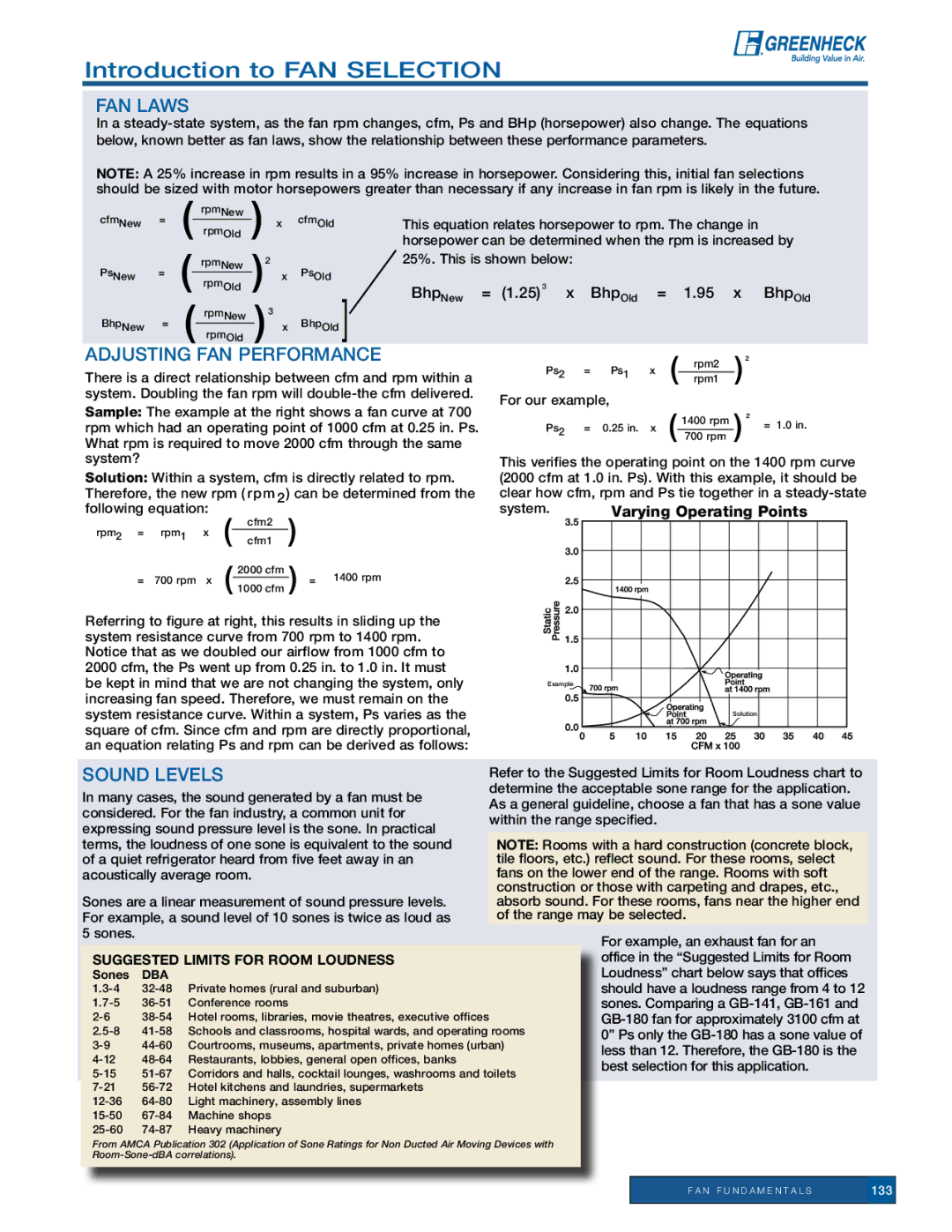
Sample: The example at the right shows a fan curve at 700 rpm which had an operating point of 1000 cfm at 0.25 in. Ps. What rpm is required to move 2000 cfm through the same system?

Solution: Within a system, cfm is directly related to rpm.

Therefore, the new rpm (rpm2) can be determined from the

following equation:

(

cfm2

)


rpm2 =

rpm1

x


cfm1


2000 cfm


1400 rpm

=

700 rpm

x

( 1000 cfm )

=


Referring to figure at right, this results in sliding up the system resistance curve from 700 rpm to 1400 rpm. Notice that as we doubled our airflow from 1000 cfm to 2000 cfm, the Ps went up from 0.25 in. to 1.0 in. It must be kept in mind that we are not changing the system, only increasing fan speed. Therefore, we must remain on the system resistance curve. Within a system, Ps varies as the square of cfm. Since cfm and rpm are directly proportional, an equation relating Ps and rpm can be derived as follows:

Ps2

=

Ps1

x

(

rpm2

)²

rpm1

For our example,


(


) ² = 1.0 in.

Ps2

=

0.25 in.

x

1400 rpm

700 rpm

This verifies the operating point on the 1400 rpm curve (2000 cfm at 1.0 in. Ps). With this example, it should be clear how cfm, rpm and Ps tie together in a steady-state

system.

Varying Operating Points


Example

Solution


Sound Levels

Refer to the Suggested Limits for Room Loudness chart to


In many cases, the sound generated by a fan must be

determine the acceptable sone range for the application.


As a general guideline, choose a fan that has a sone value


considered. For the fan industry, a common unit for


within the range specified.


expressing sound pressure level is the sone. In practical


terms, the loudness of one sone is equivalent to the sound

Note: Rooms with a hard construction (concrete block,


of a quiet refrigerator heard from five feet away in an

tile floors, etc.) reflect sound. For these rooms, select


acoustically average room.

fans on the lower end of the range. Rooms with soft


construction or those with carpeting and drapes, etc.,


Sones are a linear measurement of sound pressure levels.

absorb sound. For these rooms, fans near the higher end


For example, a sound level of 10 sones is twice as loud as

of the range may be selected.


5 sones.


For example, an exhaust fan for an


Suggested Limits for Room Loudness


office in the “Suggested Limits for Room


Sones

DBA


Loudness” chart below says that offices


1.3-4

32-48

Private homes (rural and suburban)


should have a loudness range from 4 to 12


1.7-5

36-51

Conference rooms


sones. Comparing a GB-141, GB-161 and


2-6

38-54

Hotel rooms, libraries, movie theatres, executive offices


GB-180 fan for approximately 3100 cfm at


2.5-8

41-58

Schools and classrooms, hospital wards, and operating rooms


0” Ps only the GB-180 has a sone value of


3-9

44-60

Courtrooms, museums, apartments, private homes (urban)


less than 12. Therefore, the GB-180 is the


4-12

48-64

Restaurants, lobbies, general open offices, banks


best selection for this application.


5-15

51-67

Corridors and halls, cocktail lounges, washrooms and toilets


7-21

56-72

Hotel kitchens and laundries, supermarkets


12-36

64-80

Light machinery, assembly lines


15-50

67-84

Machine shops


25-60 74-87

Heavy machinery


From AMCA Publication 302 (Application of Sone Ratings for Non Ducted Air Moving Devices with


Room-Sone-dBA correlations).


F A N F U N D A M E N T A L S

133


Page 5
Image 5
Greenheck Fan 129 manual Adjusting Fan Performance, Sound Levels, Suggested Limits for Room Loudness

129 specifications

Greenheck Fan 129 is a notable addition to the HVAC industry, recognized for its advanced technology and efficient performance. Designed primarily for ventilation, exhaust, and supply applications, the Greenheck Fan 129 excels in various commercial and industrial settings.

One of its key features is its robust construction. The fan casing is made of high-quality, corrosion-resistant materials, ensuring long-term reliability even in challenging environments. This durability is complemented by precision-engineered components, such as the impeller, which is constructed with advanced aerodynamics to optimize airflow and reduce noise levels. This focus on sound performance is particularly important in settings like schools and hospitals where acoustics are crucial.

The Greenheck Fan 129 also stands out due to its energy efficiency. It employs high-efficiency motors that meet or exceed the latest EPA and ASHRAE guidelines. This feature not only reduces operational costs but also supports sustainability efforts in organizations aiming to minimize their environmental footprint. With variable speed drive options, users can further enhance energy savings by matching fan speeds to the specific requirements of their application.

Safety and ease of maintenance are other significant considerations in the design of the Greenheck Fan 129. The fan includes access points that simplify inspections and repairs, reducing downtime and maintenance costs. Automated monitoring systems can also be integrated, providing real-time feedback on fan performance and system health to ensure that it operates at peak efficiency.

Moreover, the Greenheck Fan 129 is versatile in installation options. It can be mounted in various configurations, making it suitable for roof-mounted, wall-mounted, or inline applications. This adaptability makes it a favorite among engineers and contractors looking for reliable and flexible solutions for HVAC systems.

In summary, the Greenheck Fan 129 represents a blend of high performance, energy efficiency, and ease of use. Its durable construction, advanced aerodynamics, and safety features make it an ideal choice for a wide range of ventilation requirements. Whether for commercial buildings or industrial facilities, the Greenheck Fan 129 stands out as a top-of-the-line option for reliable and efficient airflow management.