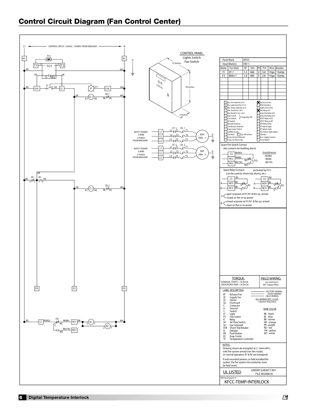
Control Circuit Diagram (Fan Control Center)

L1 CONTROL INPUT: 120VAC, 15AMPS FROM BREAKER N

H1


T1


N1


RD

T1 YW 10

TC1 12 YW T2


WH


4


5


OR

2

C

1

OR


NO


RD

S1H


S1

OR

S1

R

LT1

S1N


WH


OR

ST 1


OL 1

WH


96

95


A1

A2


G

LIGHTS FAN

CONTROL PANEL


Lights Switch

12 inches

Fan Switch


18 inches

Panel Mark:

KFCC


Hood Mark(s):

HD-1


Motor

Fan Mark

HP


Volt

PH

FLA

Wire

Breaker

F1

EF-1

1.5


460

3

3.0

14ga

15amp

F2

MAU-1

1.0


460

3

2.8

14ga

15amp


INPUT POWER

3WIRE 3 PHASE

FROM BREAKER

L1

L2

L3

6 inches

L1

ST 1

OL 1

T1


T1


L2

T2


T2

EXH

G

L3


T3


T3

FAN

1


#1 Qty. Fan Switches (0-3)

#1 Qty. Light Switches (0-3)

#0 Qty. Temp. Switches (0-1)

1One Switch for L & F

IOne Breaker Con. L & F

H

Heat Switch


Tempering SW

C

Cool Switch


YAD Switch

XRemote Switches

PPushbutton Switches

VEvap Cooler Switch

AAudible ALarm

R

Gas Reset

Q

Gas O￿ w/Fans


GPower for Gas Solenoid

BPower for Shunt Trip

2

M

L

-9

F

T

S

E

O

J

K

N

D

U

W

Exhaust in Fire

MUA Interface Lights Out in Fire Fire Relay (#1) Extra Fire Relay (#2) Extra Fire Relay (#3) DPDT Relay w/SF DPDT Relay w/EF O￿ Delay Relay SF Failure Light EF Failure Light

Fan Failure Light (Appl.) Damper

Aux. Supply Contact Tie in WWCP


OR


RD

R1

R1

YW


4

1

1

3


YW

ST 2


OL 2

WH


96

95


A1

A2


D3


D1


D2

RD


C1 RD(RD)

FS1

BR(BK)

NC1

BR

R1


WH


7


C

NC


2


R2


2

7


BK(YW)

NO1


NO


INPUT POWER

3WIRE 3 PHASE

FROM BREAKER

L1

L2

L3

L1

ST 2

OL 2

T1


T1


L2

T2


T2

SUP

G

L3


T3


T3

FAN

2


Spare Fire Switch Contact

(dry contacts for building alarm)


RD(RD)


Ansul(Amerex)


C2


RD(RD)


BR(BK)


NC2

NC


C

FS2

BR(BK)


BK(YW)


BK(YW)


NO2


NO


Spare Relay Contacts


(activated by FS1)


(can be used for shunt trip, alarms, etc.)


RD


RD


C3


C4


A


NO3

BR


A

NO4

BR


B


NC3

BK 4


1

R2

B

NC4

BK 5


8

R2


3


6


open w/power at H1/N1 & ￿re sys. armed A closed on ￿re or no power

closed w/power at H1/N1 & ￿re sys. armed B open on ￿re or no power


TORQUE:


FIELD WIRING:

TERMINAL STRIPS = 18 IN/LB.


use minimum

GROUNDING BAR = 20 IN/LB.


60° Copper Wire


LABEL DESCRIPTION


FACTORY WIRING

EF

Exhaust Fan


HOOD WIRING

SF

Supply Fan


FIELD WIRING

ALL WIRING 90°C 14 GA.

ST

Starter

OL

OverLoad

UNLESS SPECIFIED

C

Contactor


G

Ground


WIRE COLOR

S

Switch


BK - black

LT

Light


FS

Fire Switch


BL - blue

R

Relay


BR - brown

AF

Air Flow Switch


OR - orange

SV

Gas Solenoid


PR - purple

STB

Shunt Trip Breaker


RD - red

D

Damper


YW - yellow

PB

Push Button


WT - white

EC

Evap Cooler


TC

Temperature Controller


NOTES:

Drawing shown de-energized at L1 (term.#H1), with ￿re system armed (non-￿re mode).

(in normal operation, R1 & R2 are energized)

If wall mounted prewire, or ￿eld installed ￿re system, the ￿re system microswitches must

be ￿eld wired.

UL LISTED

UNDER SUBJECT 891

FILE #E200616


Wiring Diagram #

KFCC-TEMP-INTERLOCK

6 Digital Temperature Interlock

®

Page 6
Image 6
Greenheck Fan 474750 specifications Control Circuit Diagram Fan Control Center, Control Panel, Field Wiring

474750 specifications

The Greenheck Fan Model 474750 is a high-performance ventilation solution designed for a variety of commercial and industrial applications. This fan is particularly known for its reliable operation, energy efficiency, and robust construction, making it an ideal choice for facilities that require adequate air movement and control.

One of the standout features of the Greenheck Fan 474750 is its advanced aerodynamic design, which minimizes resistance and optimizes air flow. This design results in greater energy efficiency, allowing users to reduce operational costs while maintaining effective ventilation. The fan is engineered to handle a wide range of air handling requirements, making it versatile for different environments, from warehouses to manufacturing plants.

The technology behind the Greenheck Fan 474750 includes a precision-balanced impeller, which ensures smooth operation with minimal vibration. This not only extends the lifespan of the fan but also enhances indoor air quality by preventing the introduction of unnecessary noise and disturbances in the workplace. Additionally, the fan is equipped with an energy-efficient motor designed to meet or exceed industry standards, thus ensuring compliance with energy regulations and helping reduce carbon footprints.

The construction of the Greenheck Fan 474750 emphasizes durability. Built with corrosion-resistant materials, this fan can withstand harsh environmental conditions, making it suitable for both indoor and outdoor installations. Its robust frame and casing add to its longevity, ensuring that maintenance needs are minimized over time.

Another important characteristic of the Greenheck Fan 474750 is its modular design, which allows for easy installation, maintenance, and potential upgrades. Users can easily adapt the fan to meet changing air flow requirements without extensive modification. This flexibility is particularly beneficial for facilities that may experience fluctuations in operational needs.

In summary, the Greenheck Fan 474750 stands out in the market for its energy-efficient performance, advanced aerodynamic design, durable construction, and adaptable features. Whether used in commercial or industrial settings, this fan is engineered to provide exceptional airflow while reducing energy costs and ensuring consistent reliability. Investing in a Greenheck Fan 474750 not only enhances workplace comfort but also contributes to a more sustainable operational practice.