2. SLEEVE LENGTH AND WALL/FLOOR THICKNESS

Insert the damper assembly into the prepared opening, to appropriate depth (see Page 3, Fig. 1).

Recommended maximum and minimum insertion depth can be exceeded if:

1) the operation of the damper actuator is not impeded and

2) the C of the damper blade remains within the

L

plane of the wall/floor

important safety dANGER! : To avoid causing death or serious bodily harm to building occupants, do not insert screws into the damper frame unless used for duct connection within 2 in. of the frame end.

The sleeve may extend a maximum of 16 in. beyond the wall or floor on the actuator side of the damper and a maximum of 6 in. on the opposite side.

3.DUCT TO SLEEVE CONNECTIONS

Dampers are supplied with sleeves and actuators from the factory and can be installed without the need for additional field installed sleeves.

Gauge of factory furnished sleeve determines the type of duct to sleeve connections required (see table below). Any duct connection other than the breakaway connections are considered rigid.

Sleeve Gauge

Duct Dimension

type of Duct to

Sleeve Connection


Permitted


10 ga. (0.138 in.)


14 ga. (0.075 in.)

24 in. max. dia.

Rigid or Breakaway

16 ga. (0.060 in.)


20 ga. (0.036 in.)

24 in. max. dia.

Breakaway only

Sleeve thickness must not be less than the gauge of the connecting duct.

UL Standard 555 requires all ducts to terminate at fire damper sleeves.

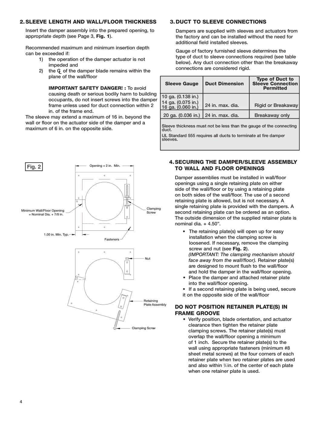
Fig. 2

0QFOJOH JO.JO


.JOJNVN8BMM'MPPS0QFOJOH

$MBNQJOH

4DSFX

/PNJOBM%JB JO


JO.JO5ZQ

'BTUFOFST

/VU

3FUBJOJOH 1MBUF"TTFNCMZ

$MBNQJOH4DSFX

4.SECURING THE DAMPER/SLEEVE ASSEMBLY TO WALL AND FLOOR OPENINGS

Damper assemblies must be installed in wall/floor openings using a single retaining plate on either side of the wall/floor or by using a retaining plate on both sides of the wall/floor. The use of a second retaining plate is allowed, but is not necessary. A single retaining plate is provided with the dampers. A second retaining plate can be ordered as an option. The outside dimension of the supplied retainer plate is nominal dia. + 4.50”.

The retaining plate(s) will open up for easy installation when the clamping screw is loosened. If necessary, remove the clamping screw and nut (see Fig. 2).

(IMPORTANT: The clamping mechanism should face away from the wall/floor). Retainer plate(s) are designed to mount flush to the wall/floor and hold the damper in the wall/floor opening.

Place the damper and attached retainer plate into the wall/floor opening.

If a second retaining plate is being used, secure it on the opposite side of the wall/floor

DO NOT POSITION RETAINER PLATE(S) IN FRAME GROOVE

Verify position, blade orientation, and actuator clearance then tighten the retainer plate clamping screws. The retainer plate(s) must overlap the wall/floor opening a minimum

of 1 inch. Secure the retainer plate(s) to the wall using appropriate fasteners (minimum #8 sheet metal screws) at the four corners of each retainer plate when two retainer plates are used and also within 34 in. of the center of each plate when one retainer plate is used.

Page 4
Image 4
Greenheck Fan SSFSDR-XXX, SEFSDR-XXX warranty Sleeve Length and WALL/FLOOR Thickness, Duct to Sleeve Connections

SSFSDR-XXX, FSDR-XXX, SEFSDR-XXX specifications

Greenheck Fan is renowned for its commitment to delivering high-quality ventilation solutions, and the SEFSDR-XXX, FSDR-XXX, and SSFSDR-XXX series exemplify this tradition of excellence. These models are designed for diverse applications in commercial and industrial environments, ensuring effective air management alongside energy efficiency.

The SEFSDR-XXX series features a unique design tailored for energy recovery applications. Its innovative structure allows for heat exchange via advanced energy recovery ventilators, making it an ideal choice for maintaining indoor air quality while reducing energy costs. The models are equipped with EC motor technology that optimizes performance by adjusting to variable load conditions, which enhances overall energy savings.

Similarly, the FSDR-XXX series is engineered for dependable performance in exhaust and supply systems. This series incorporates a robust construction that withstands harsh environmental conditions, ensuring long-term reliability. One of the standout features of the FSDR-XXX models is their acoustic performance; they are designed to operate quietly without sacrificing airflow efficiency. This is critical for applications within schools, hospitals, and offices, where noise control is vital.

The SSFSDR-XXX series offers a specialized configuration for applications requiring sanitary ventilation. These models are built with smooth, cleanable surfaces that prevent the accumulation of dust and contaminants, making them suitable for environments like laboratories and food processing facilities. The use of stainless steel construction further enhances their durability and hygiene, ensuring compliance with strict health standards.

All three series feature customizable options that allow for tailoring performance to specific project needs. This includes various fan sizes, airflow configurations, and control systems compatible with building management systems, providing users with flexibility in installation and operation.

Integration of advanced airflow modeling technologies ensures that these fans provide optimal performance under varying operating conditions. Additionally, the fans are designed with user-friendly maintenance access, which minimizes downtime during servicing.

In summary, the Greenheck SEFSDR-XXX, FSDR-XXX, and SSFSDR-XXX series are outstanding choices for any ventilation need, combining advanced technologies, durability, and energy efficiency to deliver superior air management solutions across a broad range of applications.