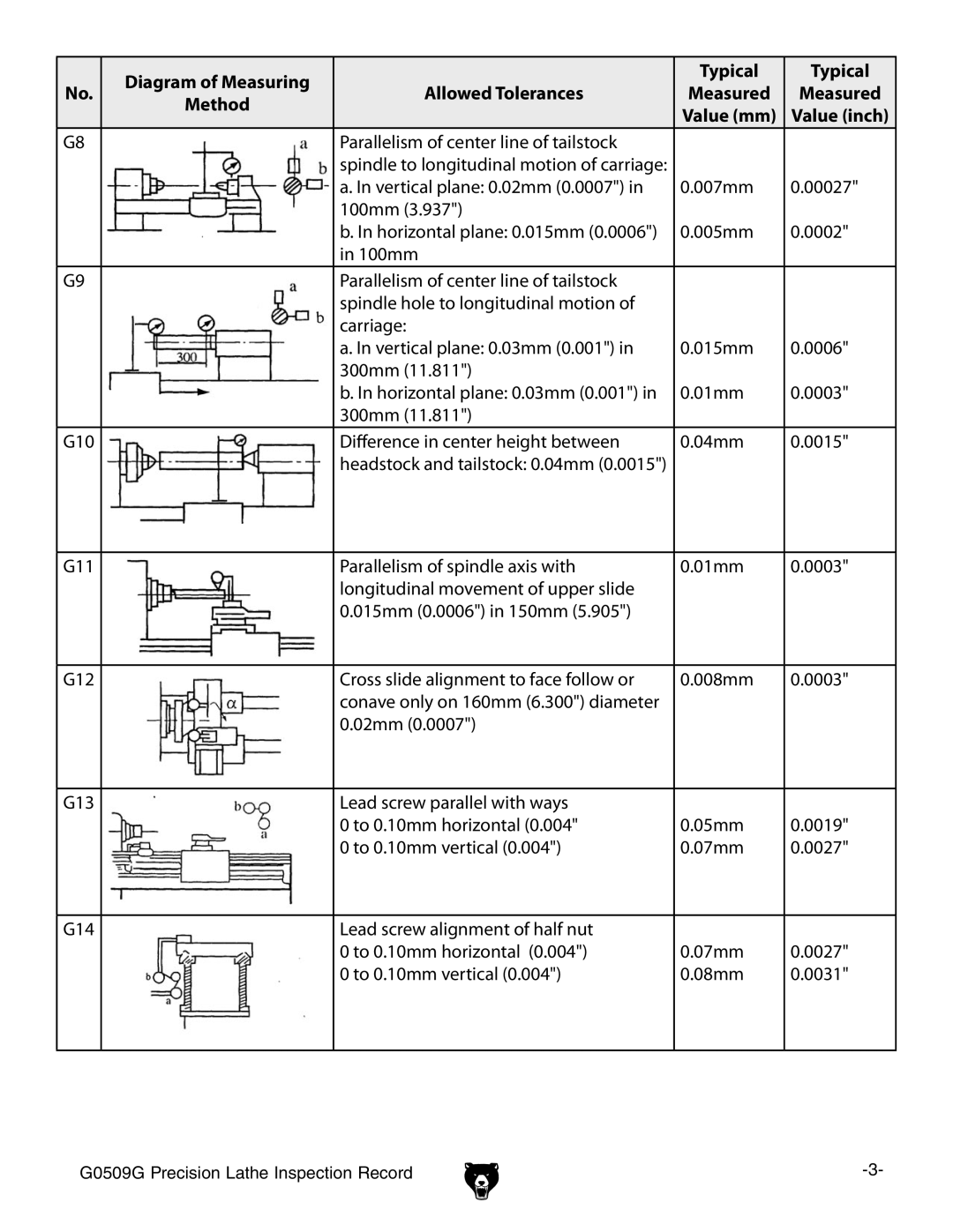
| Diagram of Measuring |
| Typical | Typical | |
No. | Allowed Tolerances | Measured | Measured | ||
Method | |||||
|
| Value (mm) | Value (inch) | ||
|
|
| |||
G8 |
| Parallelism of center line of tailstock |
|
| |
|
| spindle to longitudinal motion of carriage: |
|
| |
|
| a. In vertical plane: 0.02mm (0.0007") in | 0.007mm | 0.00027" | |
|
| 100mm (3.937") |
|
| |
|
| b. In horizontal plane: 0.015mm (0.0006") | 0.005mm | 0.0002" | |
|
| in 100mm |
|
| |
G9 |
| Parallelism of center line of tailstock |
|
| |
|
| spindle hole to longitudinal motion of |
|
| |
|
| carriage: |
|
| |
|
| a. In vertical plane: 0.03mm (0.001") in | 0.015mm | 0.0006" | |
|
| 300mm (11.811") |
|
| |
|
| b. In horizontal plane: 0.03mm (0.001") in | 0.01mm | 0.0003" | |
|
| 300mm (11.811") |
|
| |
G10 |
| Difference in center height between | 0.04mm | 0.0015" | |
|
| headstock and tailstock: 0.04mm (0.0015") |
|
| |
|
|
|
|
| |
G11 |
| Parallelism of spindle axis with | 0.01mm | 0.0003" | |
|
| longitudinal movement of upper slide |
|
| |
|
| 0.015mm (0.0006") in 150mm (5.905") |
|
| |
|
|
|
|
| |
G12 |
| Cross slide alignment to face follow or | 0.008mm | 0.0003" | |
|
| conave only on 160mm (6.300") diameter |
|
| |
|
| 0.02mm (0.0007") |
|
| |
|
|
|
|
| |
G13 |
| Lead screw parallel with ways |
|
| |
|
| 0 to 0.10mm horizontal (0.004" | 0.05mm | 0.0019" | |
|
| 0 to 0.10mm vertical (0.004") | 0.07mm | 0.0027" | |
|
|
|
|
| |
G14 |
| Lead screw alignment of half nut |
|
| |
|
| 0 to 0.10mm horizontal (0.004") | 0.07mm | 0.0027" | |
|
| 0 to 0.10mm vertical (0.004") | 0.08mm | 0.0031" | |
|
|
|
|
|
G0509G Precision Lathe Inspection Record |
