Installation
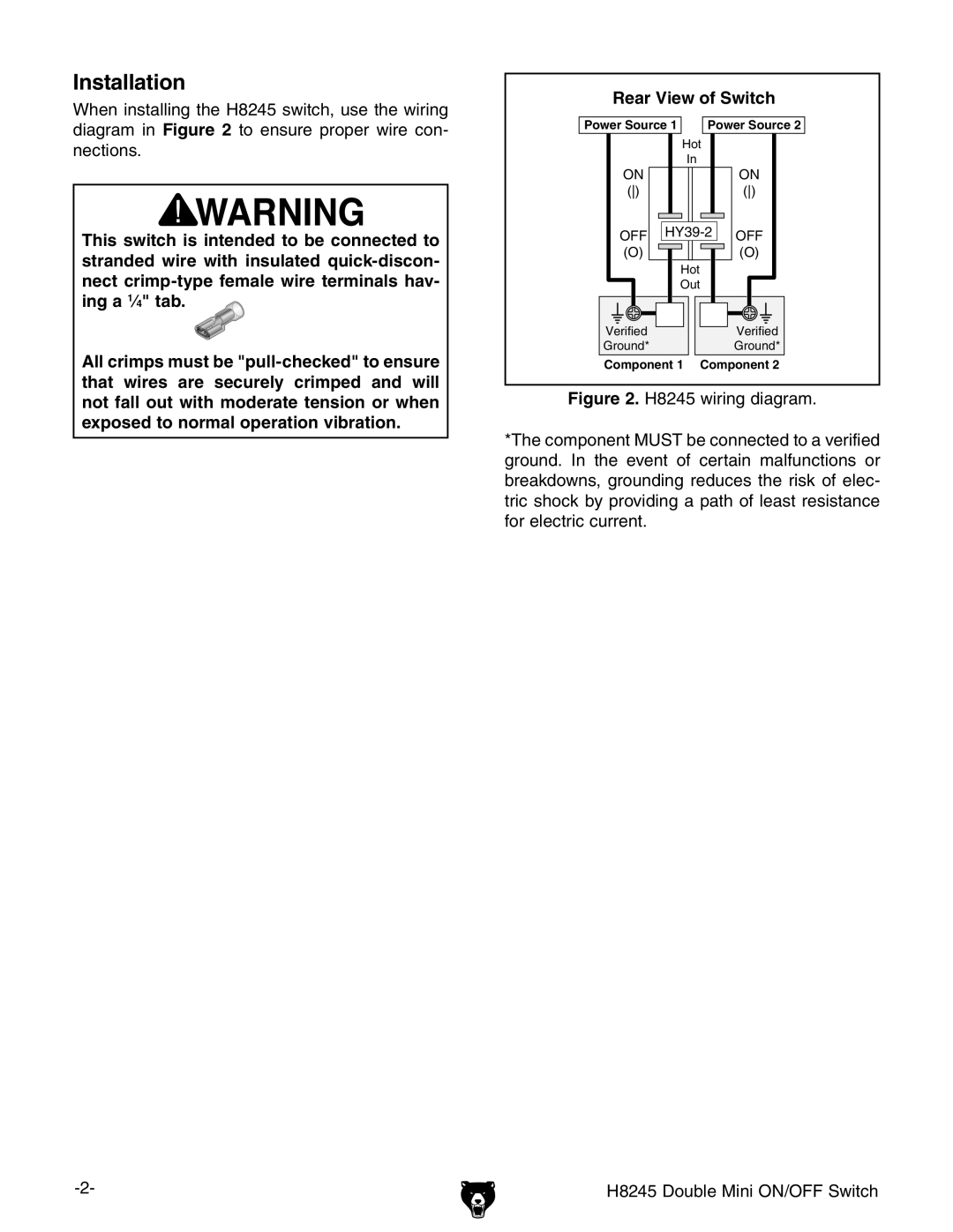
When installing the H8245 switch, use the wiring diagram in Figure 2 to ensure proper wire con- nections.
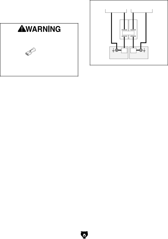
This switch is intended to be connected to stranded wire with insulated
All crimps must be
Rear View of Switch
Power Source 1 |
| Power Source 2 |
| Hot |
|
| In |
|
ON |
| ON |
() |
| () |
OFF | OFF | |
(O) |
| (O) |
| Hot |
|
| Out |
|
Verified |
| Verified |
Ground* |
| Ground* |
Component 1 Component 2
Figure 2. H8245 wiring diagram.
*The component MUST be connected to a verified ground. In the event of certain malfunctions or breakdowns, grounding reduces the risk of elec- tric shock by providing a path of least resistance for electric current.
H8245 Double Mini ON/OFF Switch |